A couple of people have asked me to repost my instructions to get all four lights to stay on, as demonstrated on my car.

.
.
These are my lights on dipped beam:
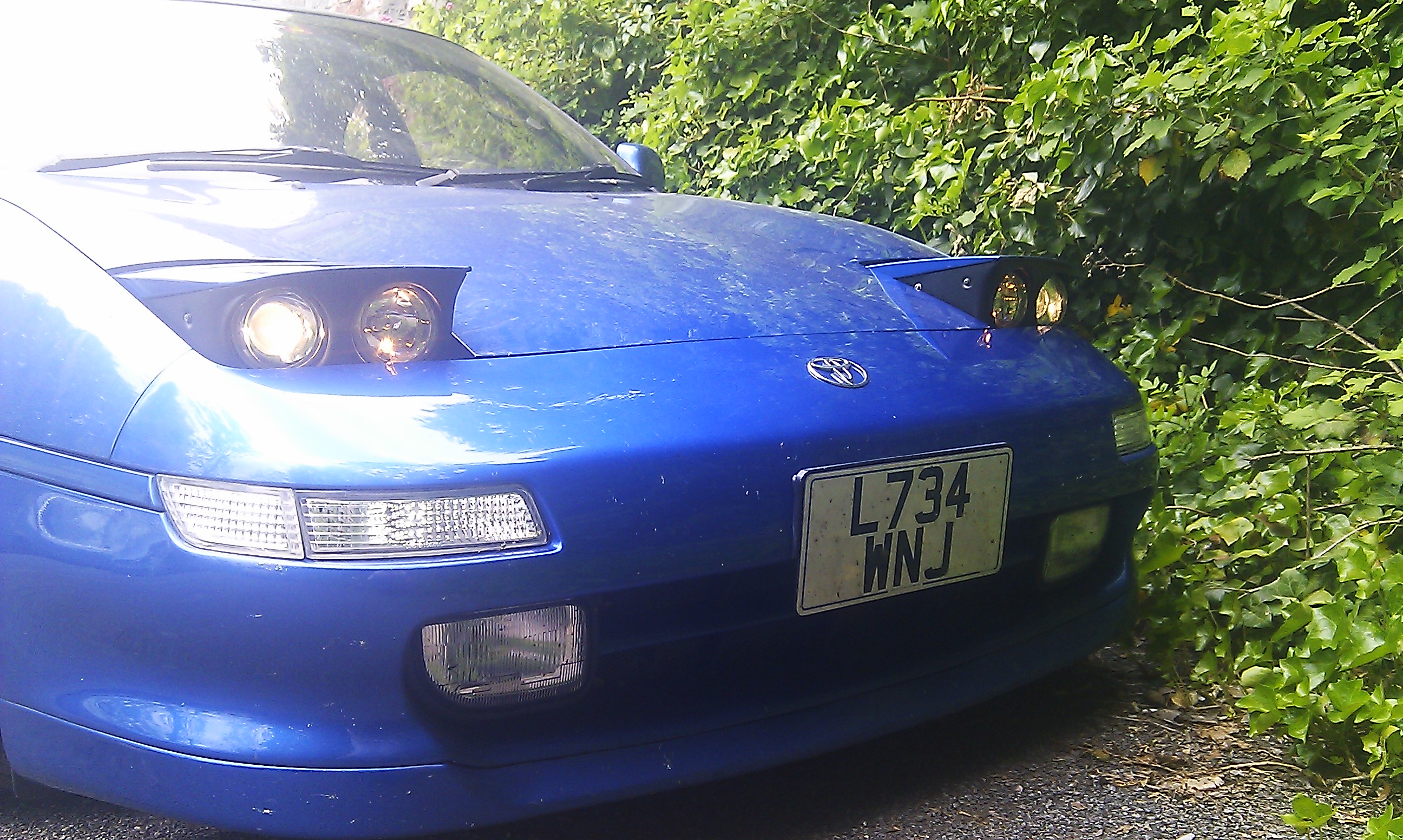
And on main beam:

Video here:
https://www.youtube.com/watch?v=fNX8-s1aEfw
As you can see, the dipped lights and the marker bulbs in the main beam units are always on, and only the main beam H7s are turned on and off.
To achieve this I did the following on both sides:
1.
Connect the red wire from the marker bulb to the red wire on the main rogue loom
2.
Cut the black wire on the rogue loom.
3.
Connect the black wire trailing from the unit and the black wire from the marker bulb to a new piece of wire
(make sure this can handle
>5A)
4.
Route the new wire through the rubber grommet, attach a ring terminal and bolt it to the chassis as a ground
At this point, your lights will behave as described above, but your main beam indicator will be inoperative.
To fix this, on one side
1.
Cut the thick red wire with a blue stripe under the steering column
(if you fail to do this, you'll blow fuses and
/ or melt wiring).
On somes cars, such as mine, this wire might have a green stripe instead.
2.
Connect three new wires to the rogue loom
- the red and blue wires, plus the hanging end of the black wire on the side of the plug
3.
Route all three wires through the grommet.
4.
Attach an automotive relay so that the red wire it attached to one side of the solenoid and one side of the switch.
Attach the blue wire to the other side of the solenoid and the black wire to the other side of the switch
If you ever take the rogue lights off, you'll need to reconnect the red and green wire, or your dipped beam won't work

I chose to solder everything, so the only crimp joints are within the frunk, away from sources of corrosion

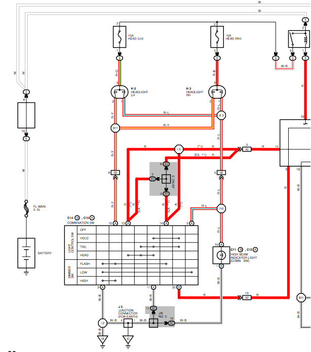
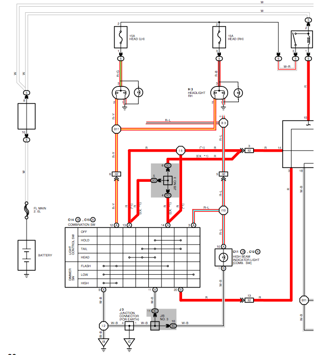
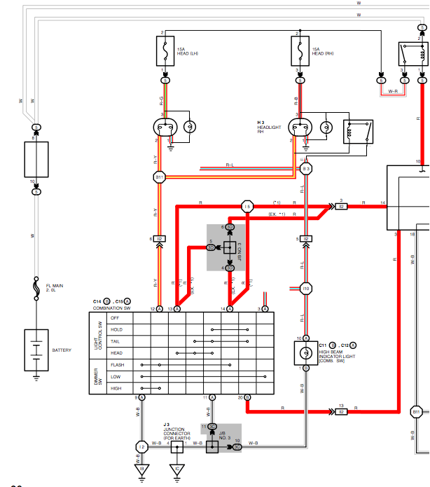
Wiring diagram for the USA car is here:
http://www.shinny.co.uk/toyota/MR2_SW_1 ... litusa.pdf
It's close but not exact.
.
.
notably, the colour code for the cut wire might be fractionally different.
I'll leave it as an exercise for the reader to work out why I cut the red wire between I10 and 3(A)

For reference, the H4 wiring loom on the rogue units is wired as such:
Red: Common 12V
(Red/Green or Red/Black on the car's wiring)
Blue: Switched main beam earth
(Red/Yellow on car's wiring)
Black: Switched dipped beam ground and 12V source for main beam indicator
(Red/Light Green on car's wiring)