AE86 digidash...
Moderators: IMOC Moderators, IMOC Committee Members
AE86 digidash...
Well, I'm finding Laurens picture of her AE86 dash quite alluring at the moment. ...so.....has anyone ever integrated an AE86 digidash into a AW11 before?
-
PW@Woodsport
- Posts: 7642
- Joined: Tue Dec 14, 2004 6:40 pm
- Location: durham
- Contact:
Re: AE86 digidash...
Not an AE86 one (as digi dashes go it's a bit plain) but i have fitted the Astra GTE ones to Mr2's which look amazing. It's hard to get them calibrated and the dash units themselves are tempermental but they really do look good.
Here's one i fitted to a Mk3 Mr2, it was all fully custom work, including making the binnacle, fitting it to a Mk1 is much easier, ignore the dancing oil pressure, i didn't have that calibrated at this point...
http://www.youtube.com/watch?v=URLHi3IsT4U
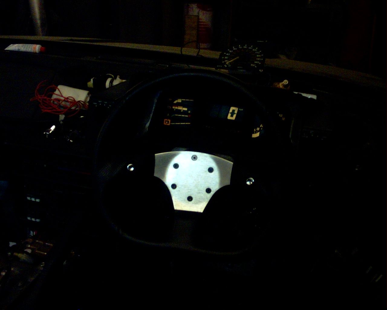
The same unit i fitted to a Mk1, it's very similar in size and shape to the original Mk1 unit and only needed minor mods to the binnacle.
Sorry for the dark pic, it was 2005 and decent camera phones hadn't been invented 
 [/img]
Here's one i fitted to a Mk3 Mr2, it was all fully custom work, including making the binnacle, fitting it to a Mk1 is much easier, ignore the dancing oil pressure, i didn't have that calibrated at this point.
http://www.youtube.com/watch?v=URLHi3IsT4U
The same unit i fitted to a Mk1, it's very similar in size and shape to the original Mk1 unit and only needed minor mods to the binnacle.
Sorry for the dark pic, it was 2005 and decent camera phones hadn't been invented

Re: AE86 digidash...
The video more than makes up for the pic!
I've just looked through UK ebay....seems the AE86 is better catered for in the mods department than the AW11, but no digidash on there at the moment.
For the Mk.1 did you have to put an electronic interface in for just the speedo?
I am banking this, and a few other ideas for a mod/track aw11 after I've had time to do all the little jobs on my SC
I've just looked through UK ebay.
For the Mk.1 did you have to put an electronic interface in for just the speedo?
I am banking this, and a few other ideas for a mod/track aw11 after I've had time to do all the little jobs on my SC
-
Lauren

- IMOC Committee
- Posts: 38632
- Joined: Mon Dec 13, 2004 5:37 pm
- Location: Greater Manchester
- Contact:
Re: AE86 digidash...
AE86 digi-dashes seem to go up for sale at around £250!
Well the ones I've seen have been at that price.
You also need some specific senders for the digi-dash too, I think, though I would expect given the engine is the same that at least it ought to be plug and play. So I would do your research on that first.
The GTE digi-dash(yes I had a 16v for 6 weeks before it got stolen) is a more impressive dash, though the read out for the revs top out at 7K, which isn't enough for the 4AGE.
AE86 dash reads till 8K rpm(same as analogue on AE86).
If you are looking for bits, try driftworks and James's forum:
http://www.phpbber.com/phpbb/index.php? ... ghtsixcouk
Also:
http://www.aeu86.org/forum/ae86
Well the ones I've seen have been at that price.
You also need some specific senders for the digi-dash too, I think, though I would expect given the engine is the same that at least it ought to be plug and play.
The GTE digi-dash
AE86 dash reads till 8K rpm
If you are looking for bits, try driftworks and James's forum:
http://www.phpbber.com/phpbb/index.php? ... ghtsixcouk
Also:
http://www.aeu86.org/forum/ae86
2020 GR Yaris - Circuit Pack 
-
Lauren
- IMOC Committee
- Posts: 38632
- Joined: Mon Dec 13, 2004 5:37 pm
- Location: Greater Manchester
- Contact:
Re: AE86 digidash...
2020 GR Yaris - Circuit Pack
Re: AE86 digidash...
Brilliant!
Thanks Lauren!
Thanks Lauren!
-
PW@Woodsport
- Posts: 7642
- Joined: Tue Dec 14, 2004 6:40 pm
- Location: durham
- Contact:
Re: AE86 digidash...
For the Mk.1 did you have to put an electronic interface in for just the speedo?
I was a bit clever with this part, i removed the original Mk1 speedo head from the clocks and kept it attached to the Mk1 cable behind the dash, then supplied the speedo head with power and earth and used its electronic speed signal output to drive the GTE digi speedo, i was rather proud of that!
It still needed to run through a speedo corrector box for calibration, i used a homebuilt Jaycar kit which worked well.
Re: AE86 digidash...
Scotsmale's MK1 with a Astra digidash


-
PW@Woodsport
- Posts: 7642
- Joined: Tue Dec 14, 2004 6:40 pm
- Location: durham
- Contact:
Re: AE86 digidash...
Ah much better pics, thanks Jimi, i think that looks fantastic, it's just getting everything calibrated that's the pain!
Re: AE86 digidash...
Any chance of a bried "how to" guide on that Paul?
Particularly the calibration issues, I have to say I have a small sum of money burning a hole in my pocket at the moment and the digi dash gave me the horn!

Particularly the calibration issues, I have to say I have a small sum of money burning a hole in my pocket at the moment and the digi dash gave me the horn!
I am going to live forever, or die trying!
Re: AE86 digidash...
Set on ebay now item no 200605312317 for £65 , i have no connection with the seller just thought i would see how much a set would cost
i think they will be hard to come buy so these maybe a steal
i think they will be hard to come buy so these maybe a steal
Re: AE86 digidash...
And another one 280518410336, but no plugs
-
PW@Woodsport
- Posts: 7642
- Joined: Tue Dec 14, 2004 6:40 pm
- Location: durham
- Contact:
Re: AE86 digidash...
Tiamat wrote:Any chance of a bried
Particularly the calibration issues, I have to say I have a small sum of money burning a hole in my pocket at the moment and the digi dash gave me the horn!
I'll have a quick go at a guide, luckily i document absolutely everything i do so i should be able to throw something useful together, big post coming up in a mo.
-
PW@Woodsport
- Posts: 7642
- Joined: Tue Dec 14, 2004 6:40 pm
- Location: durham
- Contact:
Re: AE86 digidash...
Ok here we go, please don't take this as gospel, it was some years ago i did this mod and i'm only working from my notes, so i recommend you double check all wiring on the Mk1 side with a meter, but it should be correct.
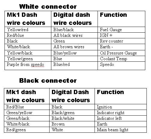
The GTE dash has two plugs, a black and a white one... this is how the wires on this dash are joined into the Mk1 dash wiring, i recommend you "T" in to the original wires instead of cutting, so you can always go back to Mk1 clocks.
That will get everything"working" except the speedo which i'll cover shortly. I say working, the readings will be all over the place, but wired correctly.
Oil pressure signal, to get this working properly i found the only way was to fit an Astra GTE oil pressure switch into the engine, luckily it had the same fitting as the Mk1 sender.
Coolant temp, nothing to do here, it works fine from the stock Mk1 sender.
Battery volts, again this just works as it should.
Tacho, works fine from the Mk1 signal.
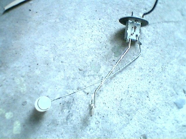
Fuel gauge, this was a problem child, it took hours to sort because the GTE clocks have such a slow lag on them for damping effect(to stop the gauge registering all over the place under G forces) but it was sorted in a fashion by extending the Mk1 float arm and bending it to get the correct zero point (tank empty), there was nothing i could do about the maximum reading, and 3/4 of a tank would register full on the GTE clocks, all it meant was it would sit at max for a long time before starting to drop, but i thought it was important that zero registered correctly.
Here is the float arm extended, crap pictures, taken with state of the art Nokia at the time
I had to bend the bump stop a little so it read lower than normal...
And the arm extended, this is trial and error i'm afraid, i took no measurements.... i'm crap i know. Luckily the sender is easy to pull in and out of the tank when adjusting it.
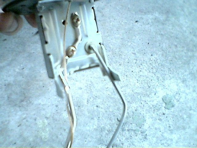
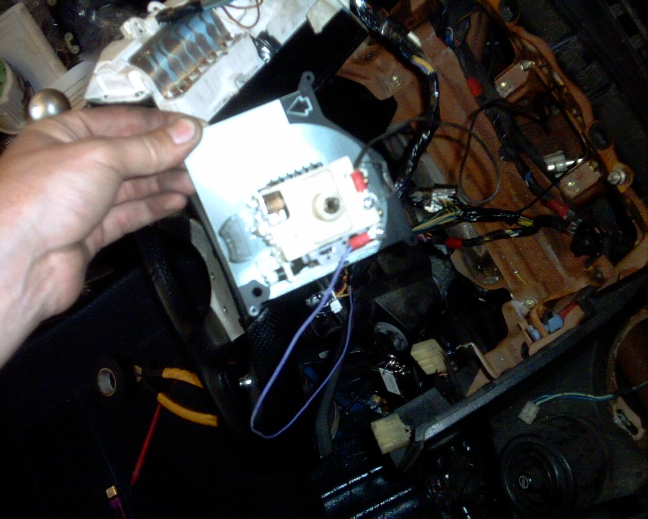
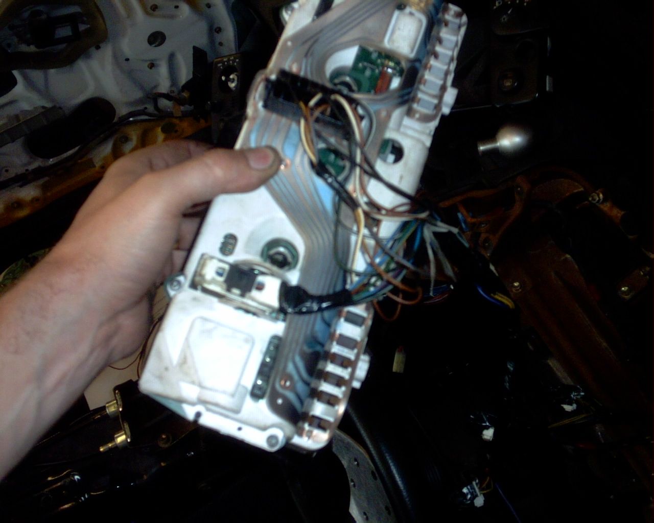
The speedo head from the Mk1 clocks needs removing and connecting up with its own earth feed and output signal wire, the black wire in this pic is earth and the purple is signal out, if you connect the purple straight to the GTE clocks it will work but will under read by 50%, so we need to send the signal into a Jaycar corrector unit and then onward to the GTE clocks.
Here is the Mk1 speedo head wired up...
Here is the Jaycar unit, available from Jaycar electronics. You have to build this yourself, it comes in kit form, so a few hours with a soldering iron....
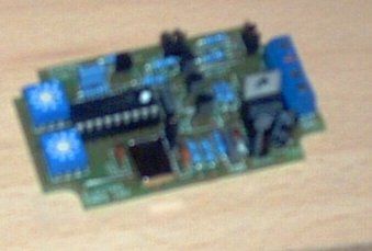
This has four wires, earth/power/signal in/signal out.
I stuck mine into an old modem housing(yes grandkids, modem!) and left the calibration pots visible, left one was tens, right one was units, and there were toggle switches for increasing or decreasing the output reading.

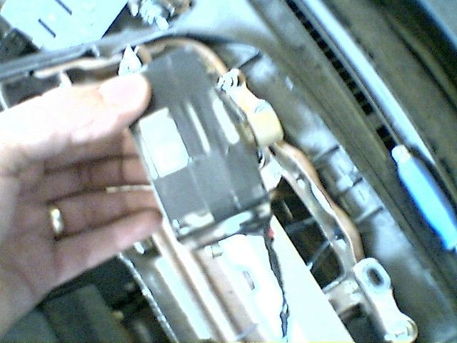
I also stuck the Mk1 speedo head into its own case and left it behind the dash with the Mk1 cable going to it....
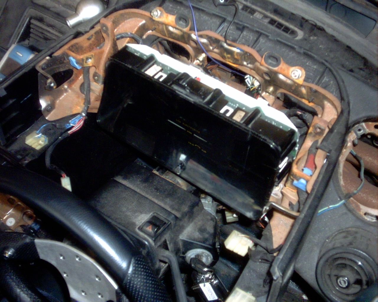
All of the wiring done....
The dash itself needs a few basic brackets making for it, not hard, and a bit of fibreglassing of the original dash binnacle to get a perfect fit, but otherwise great.
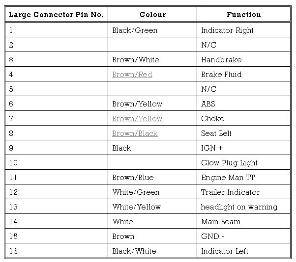
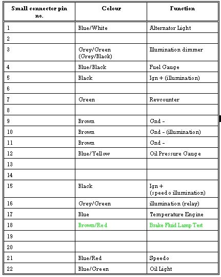
The GTE dash comes with loads of other warning lights, here are some tables of left over pins you may want to include...
That's about all i can remember folks, it's a great looking dash and well worth the effort. Here is a link to the Jaycar unit....
http://www.jaycar.com.au/productView.as ... rm=KEYWORD
A bit of work went into this, maybe add it to the KB or sticky or something i don't know.
Woods out.
The GTE dash has two plugs, a black and a white one.
That will get everything
Oil pressure signal, to get this working properly i found the only way was to fit an Astra GTE oil pressure switch into the engine, luckily it had the same fitting as the Mk1 sender.
Coolant temp, nothing to do here, it works fine from the stock Mk1 sender.
Battery volts, again this just works as it should.
Tacho, works fine from the Mk1 signal.
Fuel gauge, this was a problem child, it took hours to sort because the GTE clocks have such a slow lag on them for damping effect
Here is the float arm extended, crap pictures, taken with state of the art Nokia at the time
I had to bend the bump stop a little so it read lower than normal.
And the arm extended, this is trial and error i'm afraid, i took no measurements.
The speedo head from the Mk1 clocks needs removing and connecting up with its own earth feed and output signal wire, the black wire in this pic is earth and the purple is signal out, if you connect the purple straight to the GTE clocks it will work but will under read by 50%, so we need to send the signal into a Jaycar corrector unit and then onward to the GTE clocks.
Here is the Mk1 speedo head wired up.
Here is the Jaycar unit, available from Jaycar electronics.
This has four wires, earth/power/signal in/signal out.
I stuck mine into an old modem housing
I also stuck the Mk1 speedo head into its own case and left it behind the dash with the Mk1 cable going to it.
All of the wiring done.
The dash itself needs a few basic brackets making for it, not hard, and a bit of fibreglassing of the original dash binnacle to get a perfect fit, but otherwise great.
The GTE dash comes with loads of other warning lights, here are some tables of left over pins you may want to include.
That's about all i can remember folks, it's a great looking dash and well worth the effort.
http://www.jaycar.com.au/productView.as ... rm=KEYWORD
A bit of work went into this, maybe add it to the KB or sticky or something i don't know.
Woods out.
Re: AE86 digidash...
Paul, that's fantastic. Thanks for pioneering this for us all.
Re: AE86 digidash...
I've never heard of that before... It looks absolutely fantastic!
Re: AE86 digidash...
Paul, you're fecking gorgeous!
Now to get a paycheck in and get hunting for the dash!
Now to get a paycheck in and get hunting for the dash!
I am going to live forever, or die trying!
-
PW@Woodsport
- Posts: 7642
- Joined: Tue Dec 14, 2004 6:40 pm
- Location: durham
- Contact:
Re: AE86 digidash...
Steady on Malcolm! Ok it is pretty sexy info i'll concede that
Oh one other thing, calibrating the speedo is really easy, because you still have the original Mk1 speedo head connected to the cable you can jack the rear wheels off the ground, engage 5th and calibrate the digi dash reading via the Jaycar unit so it reads exactly what the analogue one is reading, i thought that was cool without having to drive anywhere.
Also there is a MPH/KPH switch on the GTE clocks, i think it needs to be on KPH to get the readings within range of the Jaycar unit, not 100% sure on that it's just something i seem to remember.