This forum has been retired as of 22/Aug/2021. All threads are locked. Existing users cannot log in and new users cannot register.
It remains here for posterity, and so that old links still lead to content instead of an error message.
All forum threads were migrated to the new forum. Clicking to view a thread on this forum will take you to the same thread on the new forum.
DescriptionA general Guide to LED board Creation AuthorDateTue Mar 20, 2007 4:14 pmTypePicture How-To CategoryExterior Views 4090
LED Interior Light A general Guide to LED board Creation
Ok Firstly you can use this method to create an LED board of any size shape etc and is followed up by my rear light conversion.
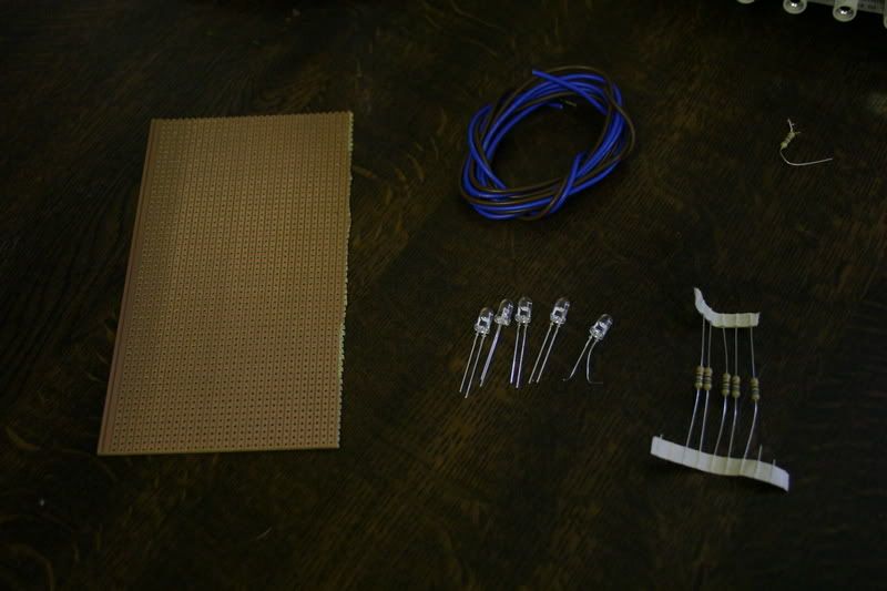
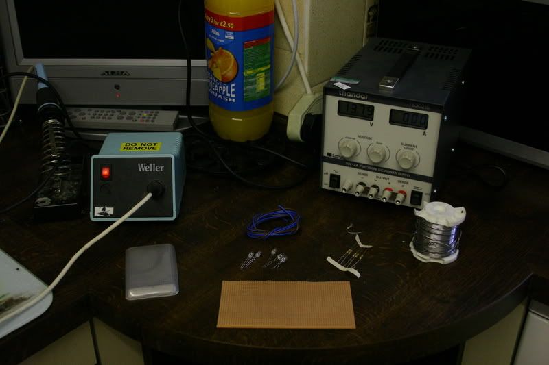
The equipment. Matrix Board (AKA Stip Board or Vero board) Single strand wire, Resistors, LED's, CuttersSolder, Iron, PSU a file. (Can use a battery but not as safe) Lots of tea.
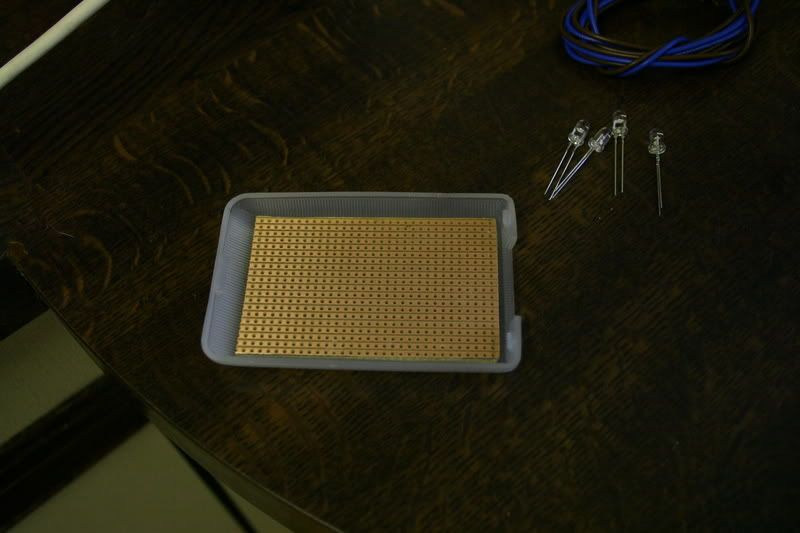
Firstly cut the board to shape. You can snap it in a vice along the holes or use cutters. File it Neat.
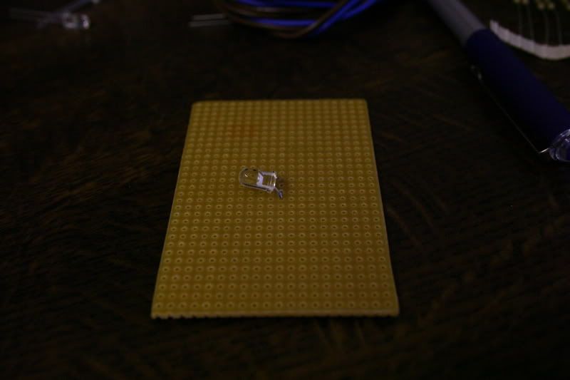
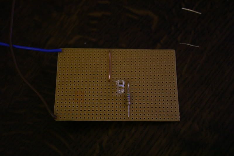
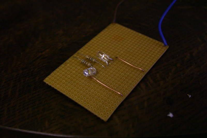
Pop the first LED in place.
Solder it in place and break the track with the small drill.
Positive wire at the top. Negative at the bottom. Link from -ve to the LED -ve. Resistor from +ve to Led +ve (one with the flag)
The resistor is calculated by voltage divided by current.
14.5V / 0.030 (30mA) = 483ohm. 470 is the nearest you can get.
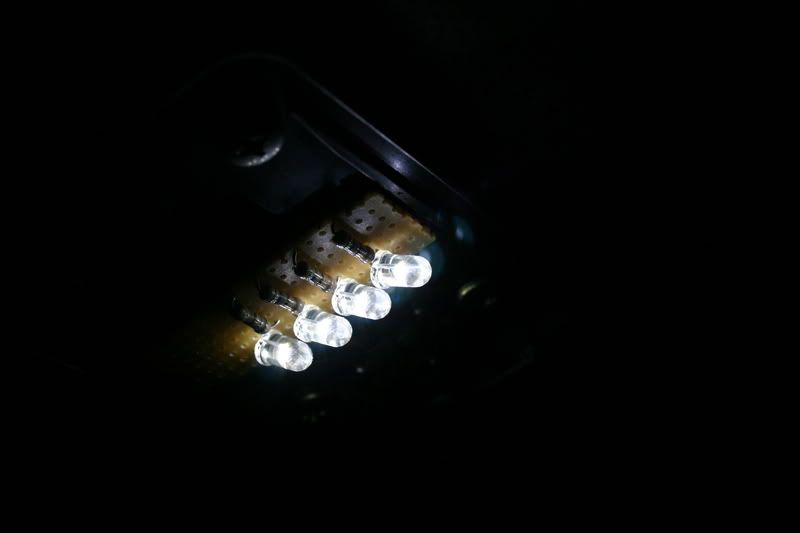
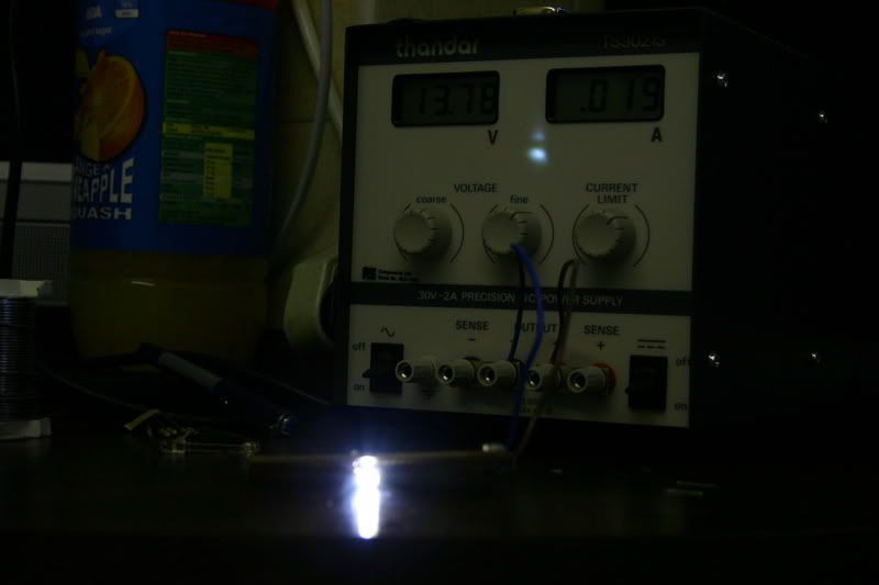
Connect to the powersupply with current limit set to 50mA for safety and one is running.
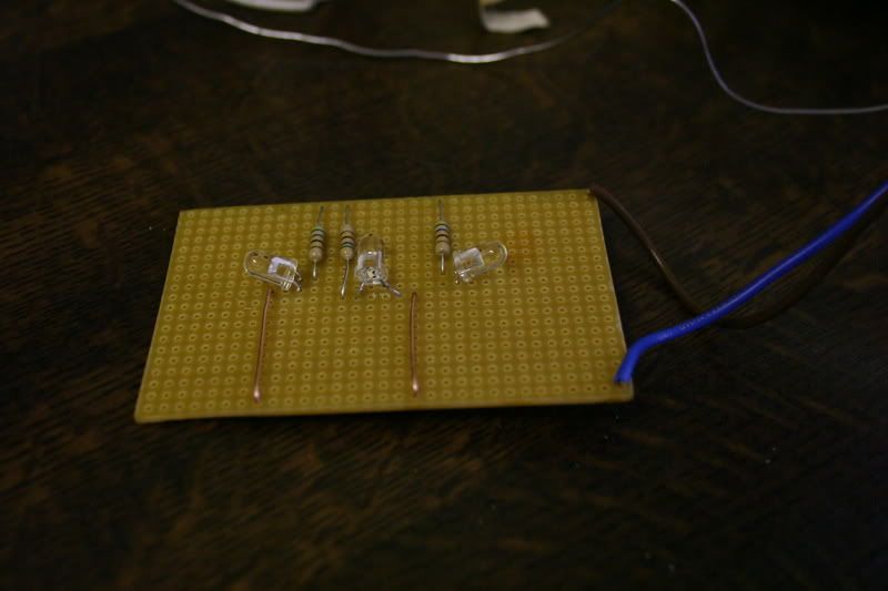
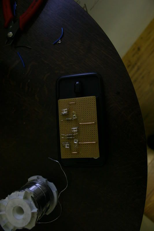
Next Place the second led in place and wire up as before
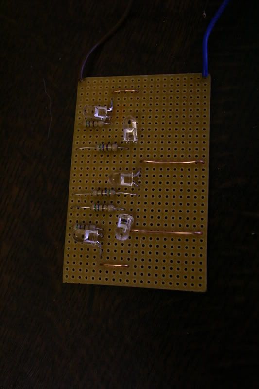
Then again until all are in place. Test each one as you go.
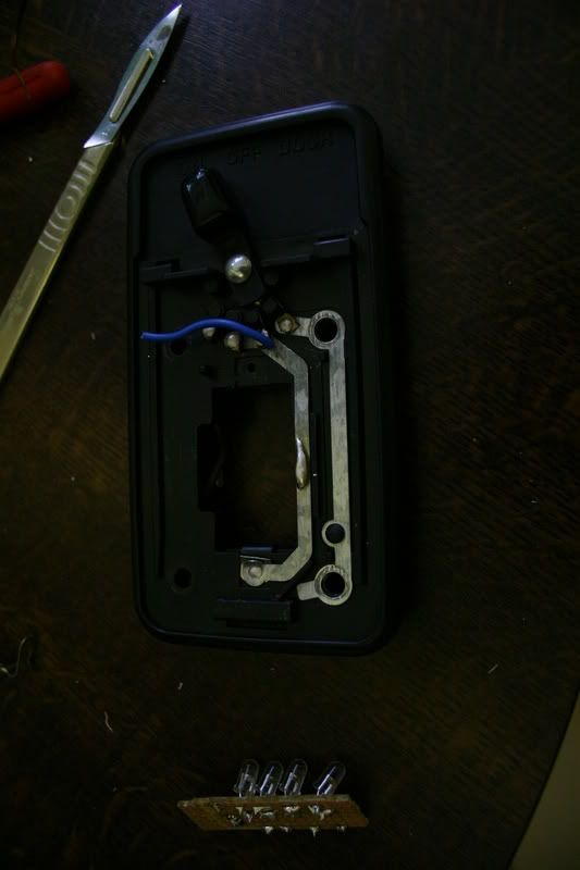
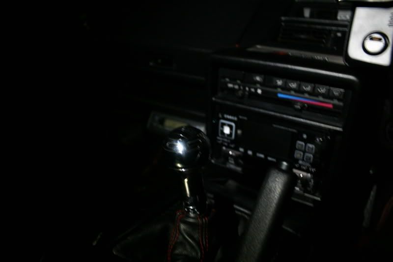
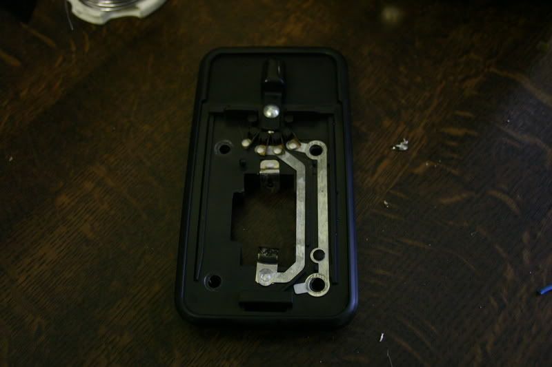
The interior light was taken out of the car by removing four screws and the connector plug.
Positive wire soldered on ready for board.
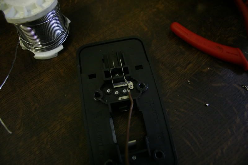
Negative wire soldered on and board put in place.
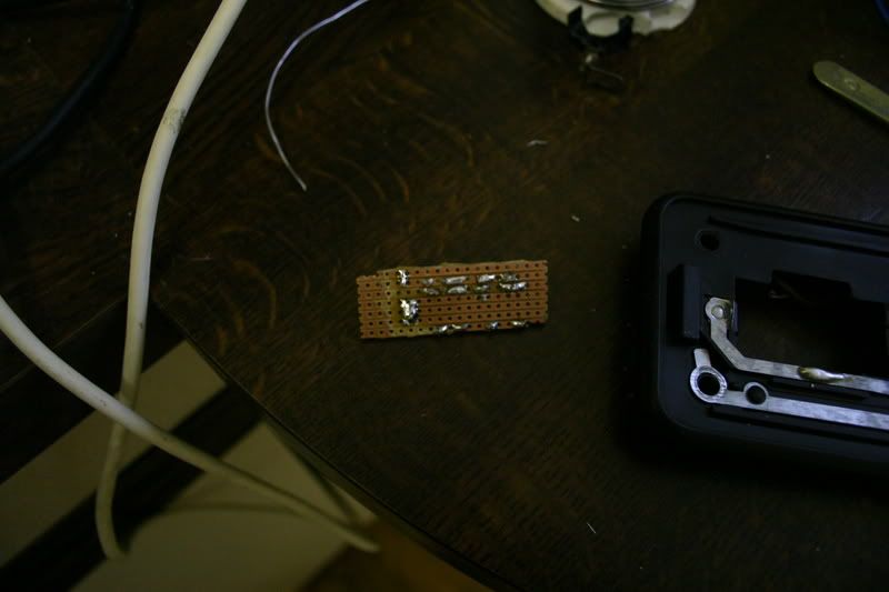
After all this work the lid did not fit on the light. .
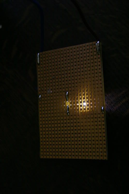
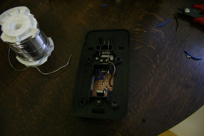
So a quick redesign and a much smaller board.
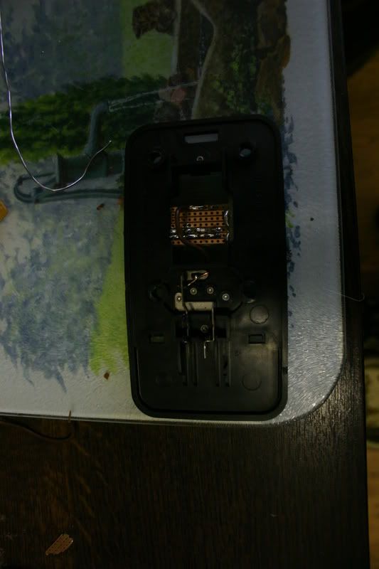
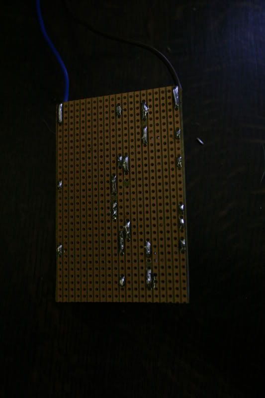
Notice the blob of solder on the metal rail.
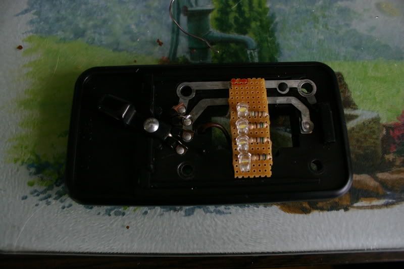
The board soldered in. The negative soldered directly from the board to the metal rail.
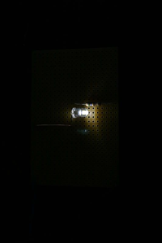
Screwed back in the car and tested.
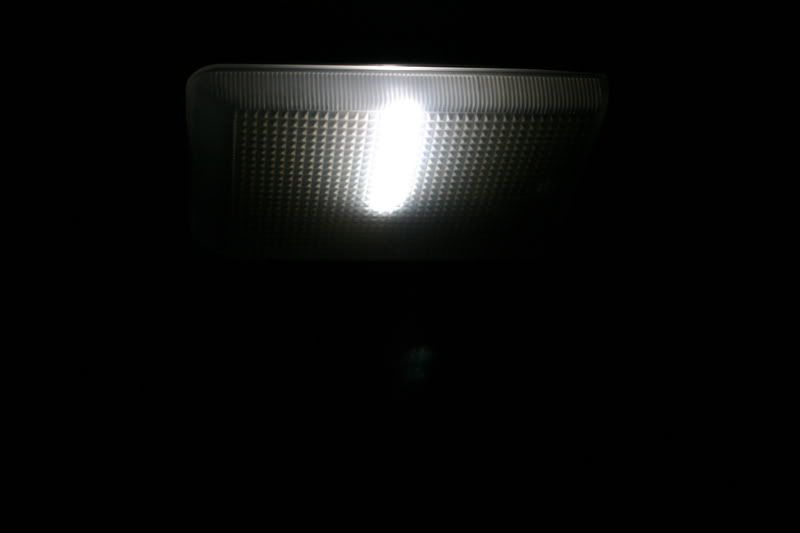
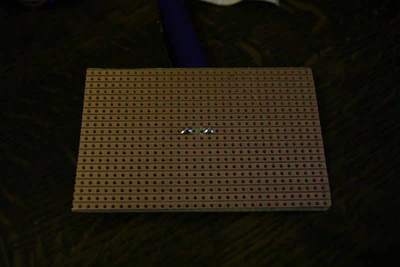
This is the light it produced. No flash used.
And finnished with the cover on.
You can create any board of any size like this. My MK1 Rear Light conversion will be on soon.
User comments
Ed: Mon Mar 26, 2007 8:00 am
An excellent write up particularly detailing how to create the circuit board. Have you done the LED conversion for your dash lights and if so have you a write up on how to do that.
Ed
midenginedmaniac: Tue Mar 27, 2007 6:12 pm
No not tried that. I have a post on LED rears and will work on the LED sidelight /Indicators next at the front.
![[d'oh!]](images/smiles/eusa_doh.gif "d'oh!") .
.