 |
|
| Changing big end and main bearings with the crank in situ |
Description Step-by-step procedure including pictures
Author Icsunonove
Date Mon Sep 18, 2006 8:45 am
Type Picture How-To
Category Engine
Views 53213
|
Changing big end and main bearings with the crank in situ
Step-by-step procedure including pictures |
 |
Changing big end and main bearings with the crank in situ
The BGB lists these procedures with the engine out of the car. However it is perfectly possible to both inspect and change both big end bearings and the main bearings with the crank in situ. This is obviously a far far easier job than removing the engine, gearbox, cylinder head and dismantling the engine. In fact it is a fairly simple job. The only problem is that you can't preorder the bearings prior to removing the sump. I still recommend you consult the BGB, but hopefully these pictures and tips will help. ![[Very Happy]](images/smiles/icon_biggrin.gif "Very Happy")
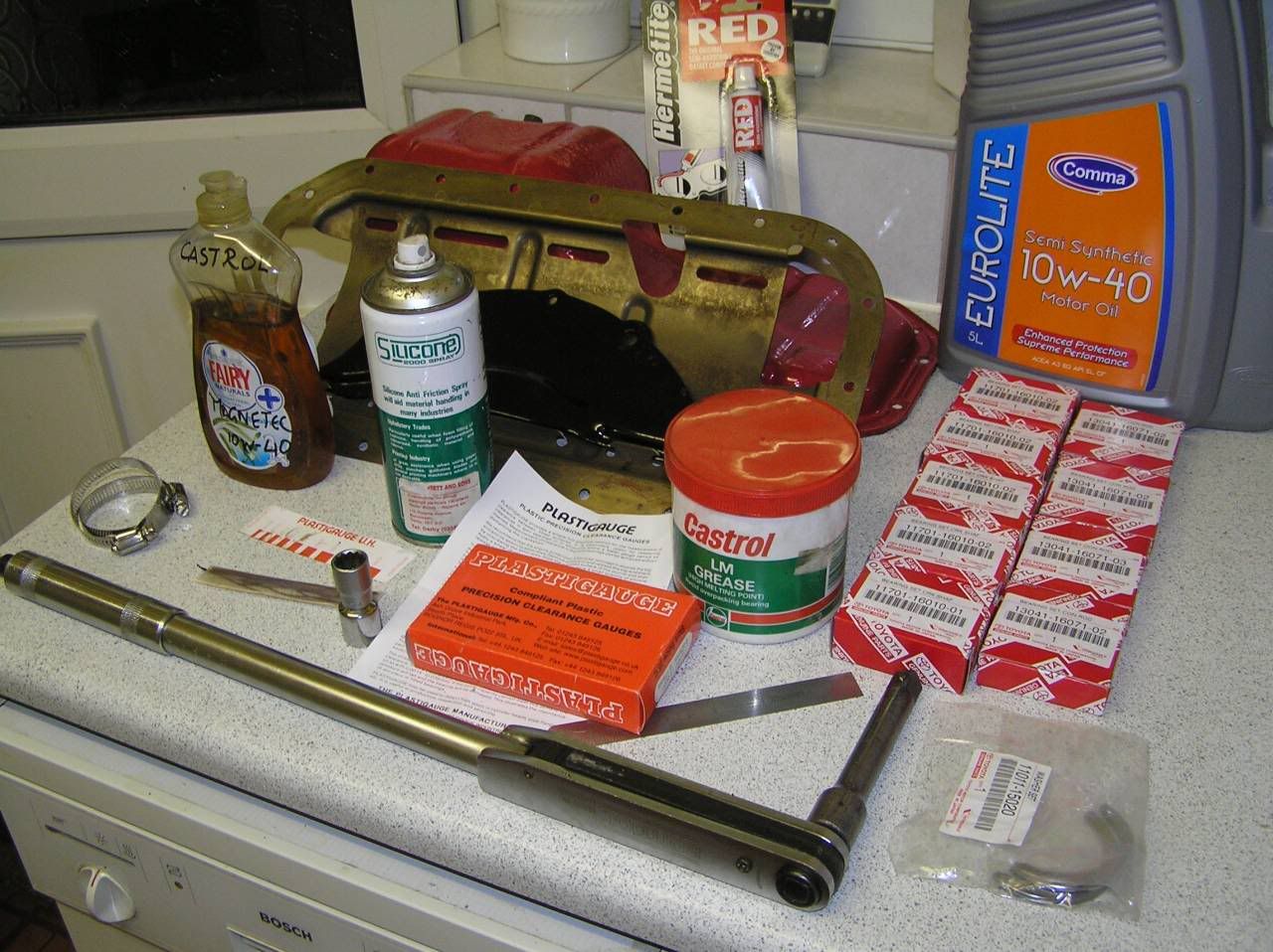
Stuff you'll need:
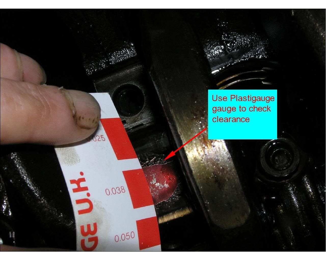
Socket set with 10mm and 14mm sockets
14mm Bi-hex socket (for big end caps)
Torque wrench (capable of 60Nm)
5 off Main bearings (size to be established during procedure)
4 off Big End bearings (size to be established)
1 off set of Thrust bearings (one size only)
Plastigauge set
Silicon spray (for releasing cap after Plastigauge test)
LM Grease (for holding Plastigauge slug on crank)
Hermatite Red sealant (or equivalent for sealing sump and baffle)
Oil (for assembly and refilll)
6" Steel rule (for removing top shells)
Jewellers flat blade screwdriver (for removing top end caps)
Errrrm, can't think of anything else
(Note: Click on each photo for a bigger picture! )
1) Buy a set of car ramps!
2) Reverse your car onto the ramps.
3) Chock the front wheels and release the handbrake and take the car out of gear.
4) Remove the spark plugs and cover the spark plug holes to prevent ingress of dirt.
5) Remove the centre section of the exhaust. There are three (12mm A/F') nuts holding the centre section to the downpipe and a U-bolt clamping the centre section to the backbox. Drain the oil from the sump.
5a) Fully slacken the alternator/water pump belt (4AGE) or both belts (4AGZE)
6) Remove the lower flywheel cover, two 14mm A/F and two 10mm A/F setscrews
7) Release the sump by removing the 19 off 10mm A/F setscrews and 2 off 10mm A/F nuts
8 ) The sump may be stuck to the baffle plate. Using a soft faced hammer hit the sump to break the seal. If this method doesn't work use a Stanley knife blade to cut the seal between baffle and sump.
9) Remove the sump
10) Remove the suction strainer by removing the two setscrews retaining the support legs and the the two setscrews making the seal.
11) Carefully remove the suction strainer assembly if possible retaining the gasket in tact.
12) Remove the baffle plate. This is sealed to the block with sealant. It slightly overhangs the block profile so you can use a Stanley knife blade to cut the seal if necessary
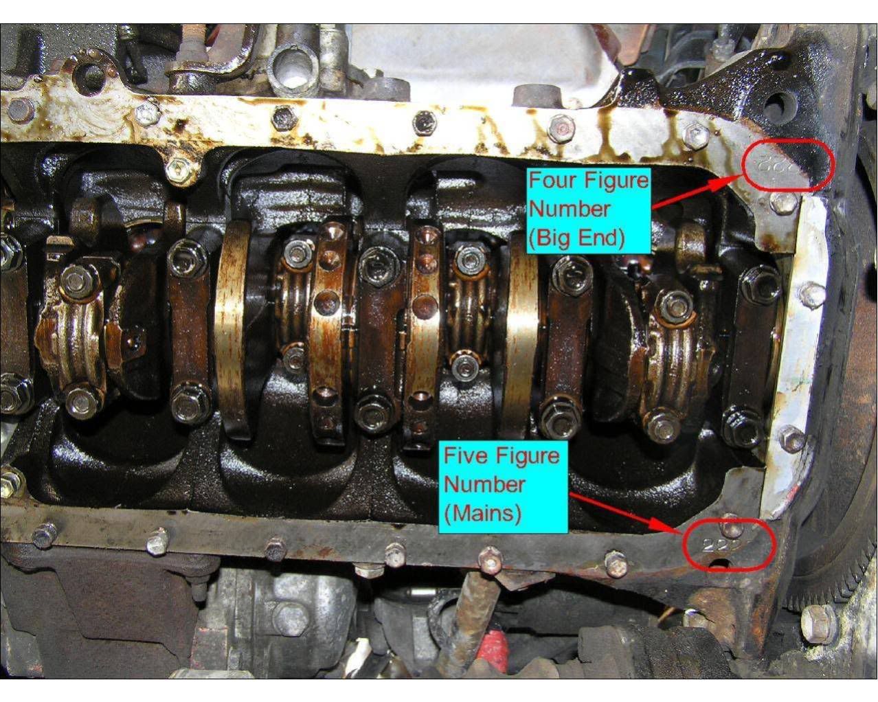
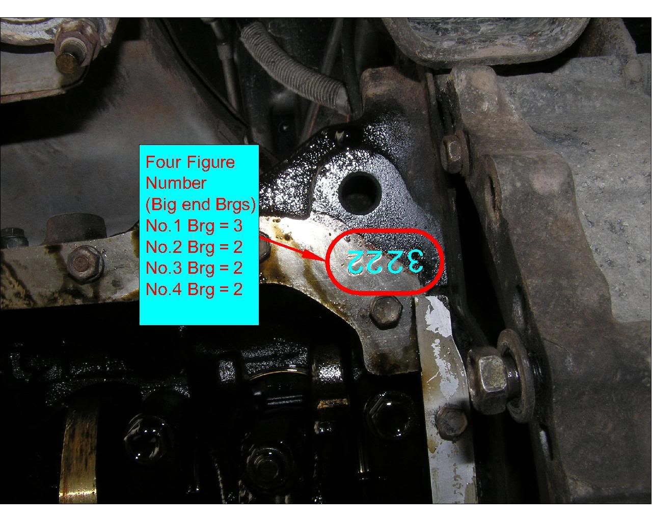
13) Once the baffle is off you will be able to see two sets of numbers stamped onto the underside of the block near to the flywheel end. The five figure number is needed (in conjunction with the numbers on the crank) to establish the class of the each of the main bearings. The four figure number is the class of big end bearings. Make a note of these two numbers, you will need them for reordering new bearings (unless you need to regrind the crank ![[Rolling Eyes]](images/smiles/icon_rolleyes.gif "Rolling Eyes") ) )
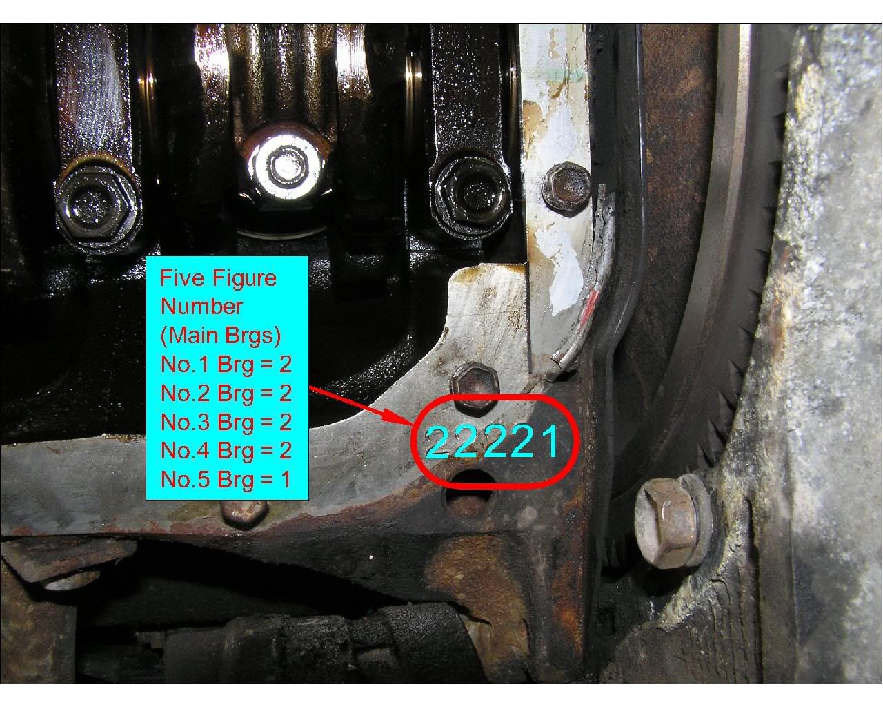
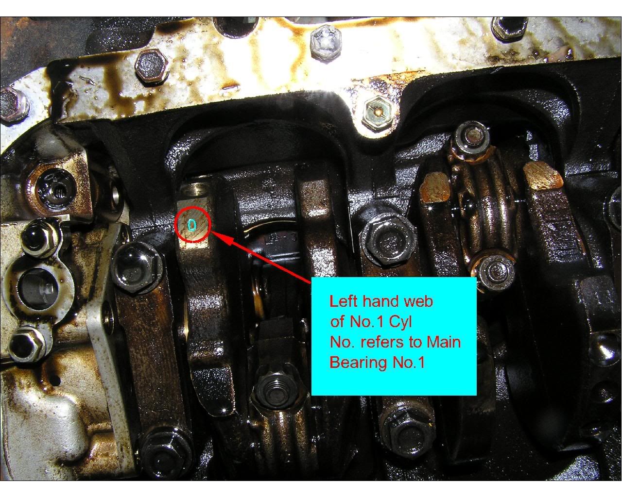
13a) Rotate the crankshaft until you can see some numbers stamped onto the crank webs. There is one number stamped on left hand web of number 1 cylinder. There are two numbers stamped on the right hand web of no.2 cylinder and two numbers stamped on the left hand web of no.3 cylinder. Make a note of these numbers, they are needed in conjunction with the five figure number for the main bearings
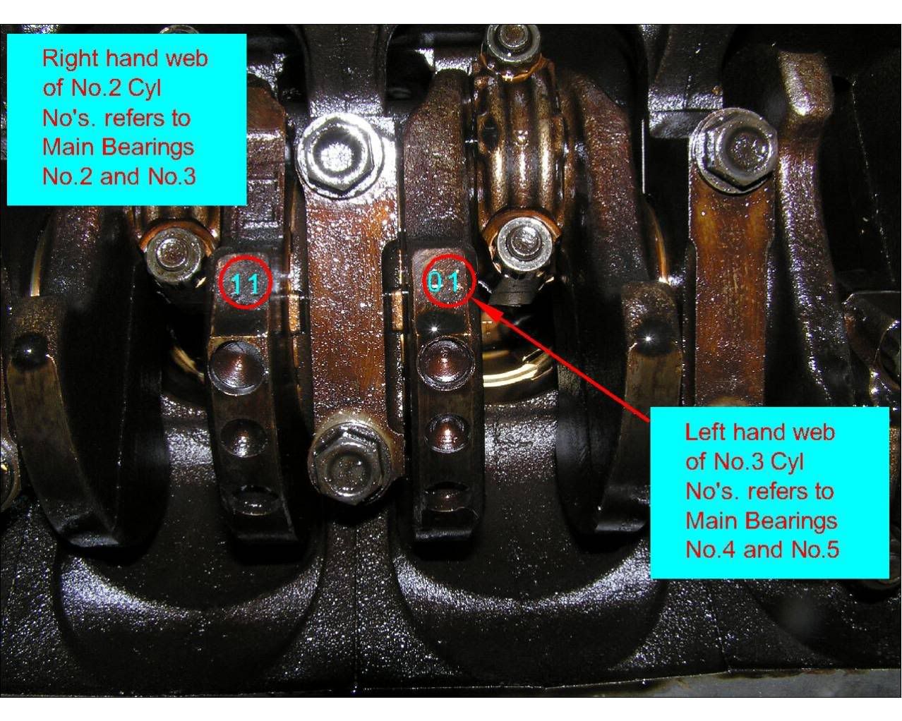
13b) To get the correct main bearing size required you need to sum up the number on the block and the numbers on the crank. In this case the number on the block was: 22221. The numbers on the crank were: 01101. Summing up the numbers required are: (2+0) = 2, (2+1) = 3, (2+1) = 3, (2+0) = 2, (1+1) = 2. So: 23322
14) Using a bi-hex (or 12 point) 14mm socket remove each of the big end bearing caps in turn.
14) Visually inspect the crank journals and check it is not damaged. Remove the top big end shell by using a jewellers flat-bladed screwdriver behind the anti-rotation tag. Inspect the shell bearings for visible damage. Assuming everything is ok continue to next procedure to accurately check the bearing clearances.
16) To check the big end clearances accurately you need to purchase some Plastigauge. With the engine (or rather the pistons and con rods) in situ there simply isn't any other way of accurately measuring this.
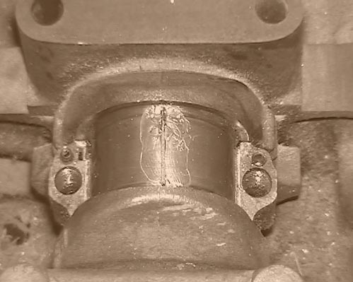
17) Clean each crank journal thoroughly. Cut a piece of Plastigauge to the length of the journal. Coat the plastigauge slug with some grease. Stick the Plastigauge slug to the journal, the grease being used to hold the gauge onto the crank. Clean the big end lower bearing and spray on some Silicone release spray (oil will probably do)
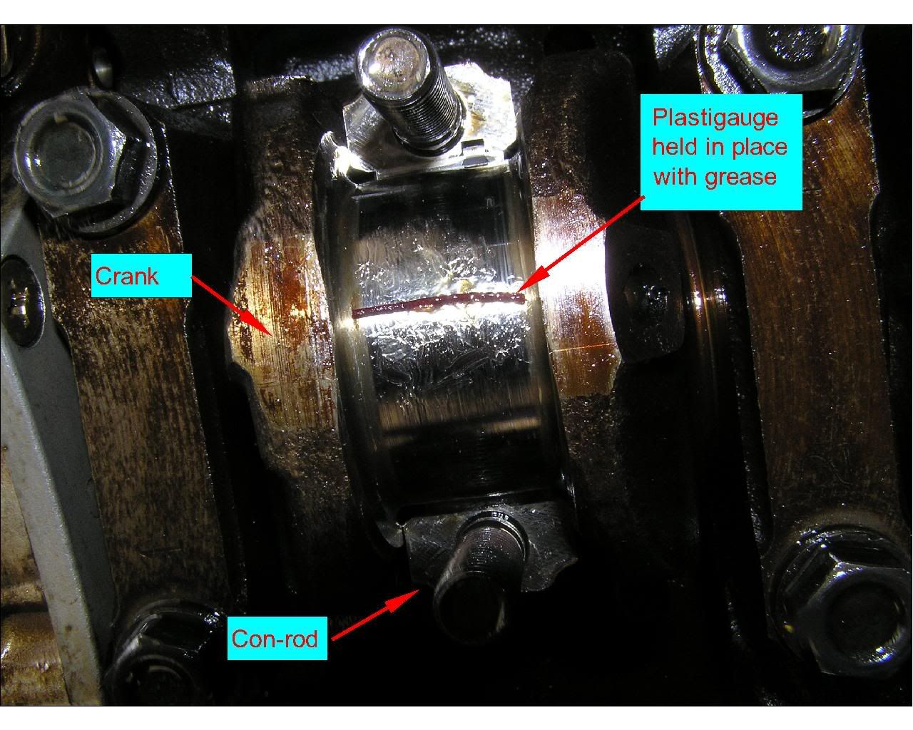
18 ) Refit the the lower big end cap and tighten to the recommended torque. Then remove the lower cap.
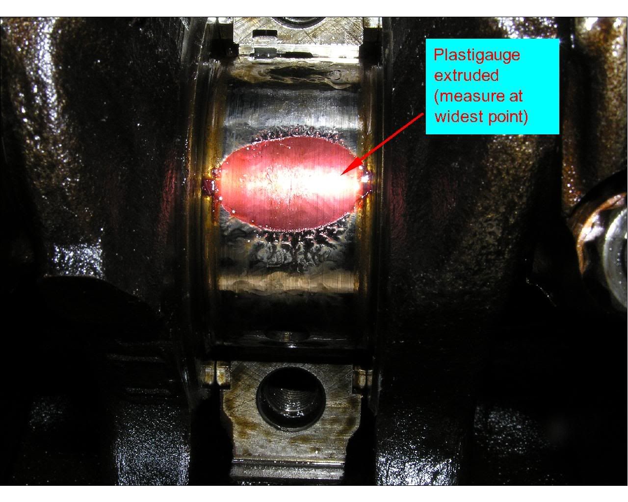
19) Inspect the results by using the Plastigauge calibrated ruler.
20) While the sump is off it makes sense to check the main bearings at the same time. Slacken the main bearing caps in the correct sequence (outermost first - working inwards). Leaving No.3 cap hand tight to support the weight of the crank, remove the other four and fit plastigauges. Hand tighten the caps to support the crank and then release No.3 cap and also fit a plastigauge. Tighten in the correct sequence to the recommended torque. Slacken caps in the correct sequence and inspect the results (always ensuring the crank is supported by at least one cap).
21) If you need to change the main bearings it can be done with the crank in situ. The BGB does not explain this. Always make sure one cap is hand tight to support the crank. To remove the top main bearing shell you need to rotate it 180 degrees. The anti-rotation tag means that it can only be done in one direction. Using a 6" steel rule and a small hammer gently tap the bearing to force it to rotate as far as you can. Be extremely careful not to scratch the crank. Using a screwdriver (carefully) on the outside of the bearing you can lever the bearing to rotate it further. Once rotated through 180 degrees you can remove the bearing.
22) To refit the main bearings the procedure is basically the reverse of disassembly. However it may appear difficult at first to get the top main bearing shell fitted. But if you look carefully the shell is very slightly tapered in thickness towards the split points. So when refitting the top bearing slightly hold the tagged end away from the crank and it will enter (insert diagram / picture)
23) After changing big ends and / or main bearings I strongly recommend Plastigauging everything again just to make absolutely sure that everything is ok. The consequence of it not being correct means potential crank damage, meaning a much, much bigger job.
24) Finally retorque the main bearing caps in the correct sequence (innermost outer) to XX Nm
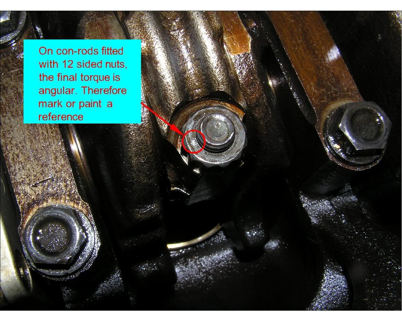
25) Retorque the main bearing caps. For hexagon nuts tighten to XX Nm. For 12-sided nuts, torque to 40Nm and mark the nut with paint or a pop mark. Then tighten an additional 90 degrees.
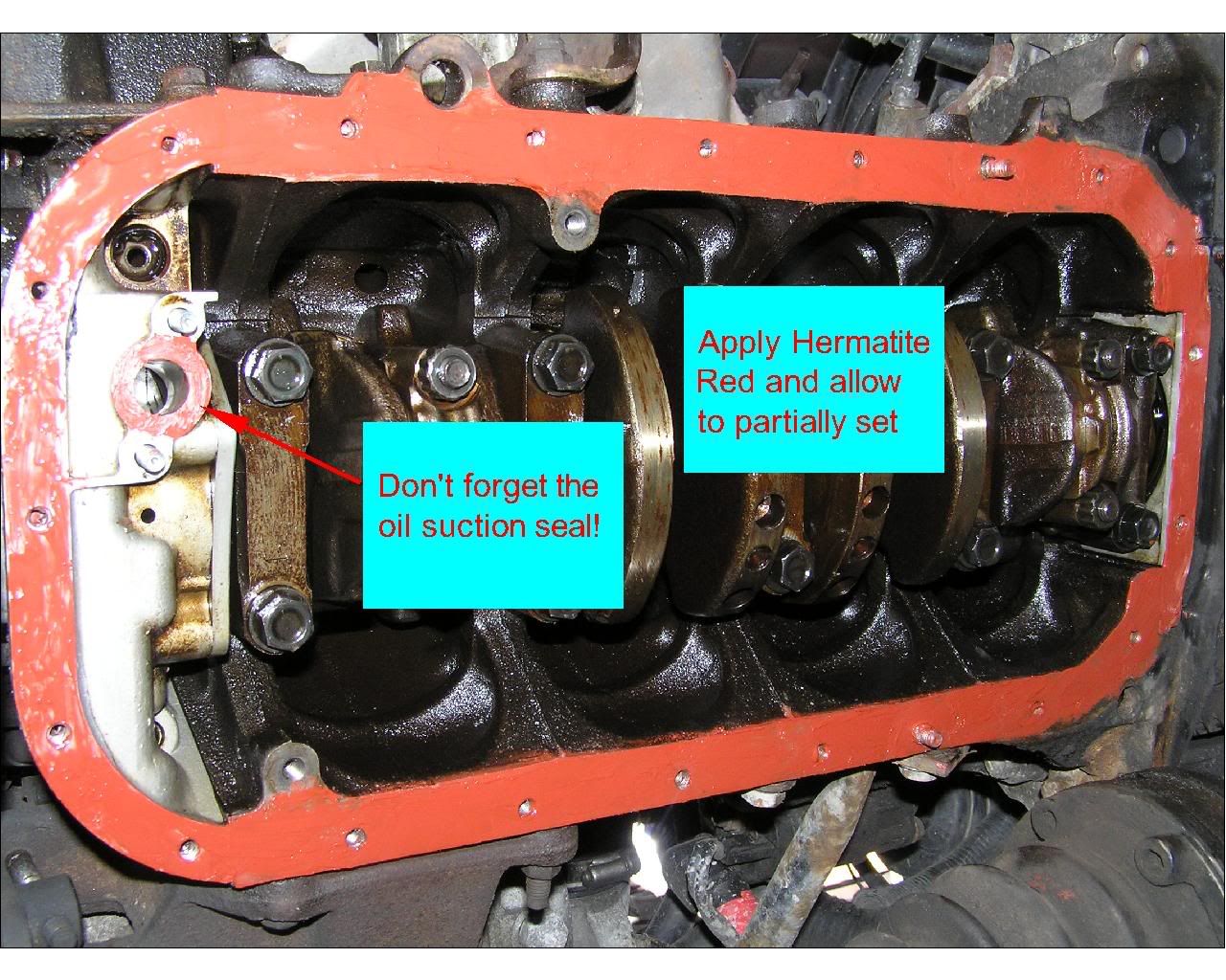
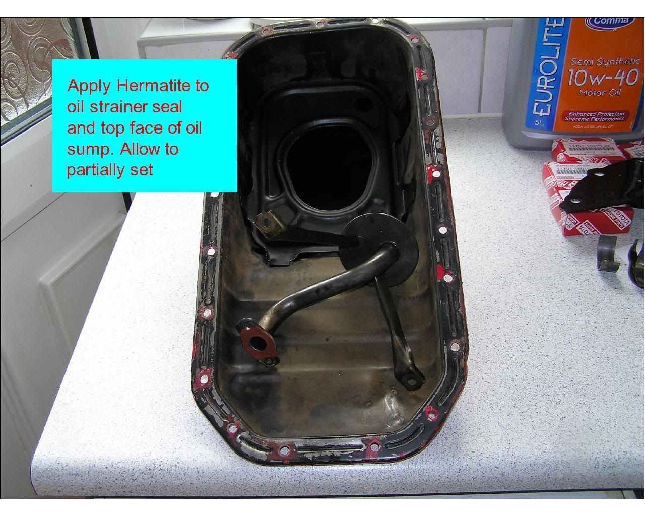
26) Clean the bottom of the block and apply sealant. If using Hermatite Red allow time for solvent to evaporate. Do not forget to apply sealant to the oil suction hole, this seal is absolutely crucial to your engine!
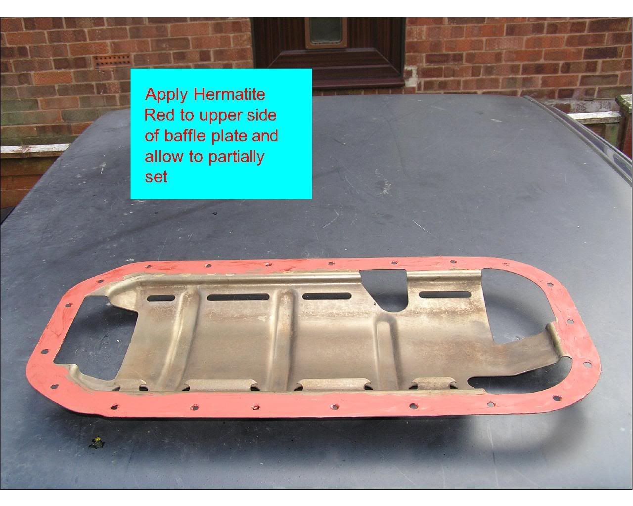
27) Apply sealant to the top side of the baffle and allow solvent to evaporate.
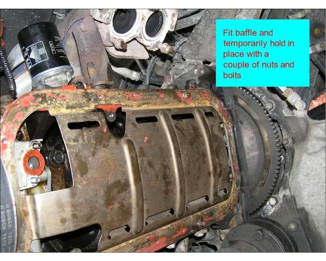
28 ) Fit baffle and temporarily hold in place with a couple of nuts and bolts
29) Apply sealant to sump and seal on oil strainer pipe.
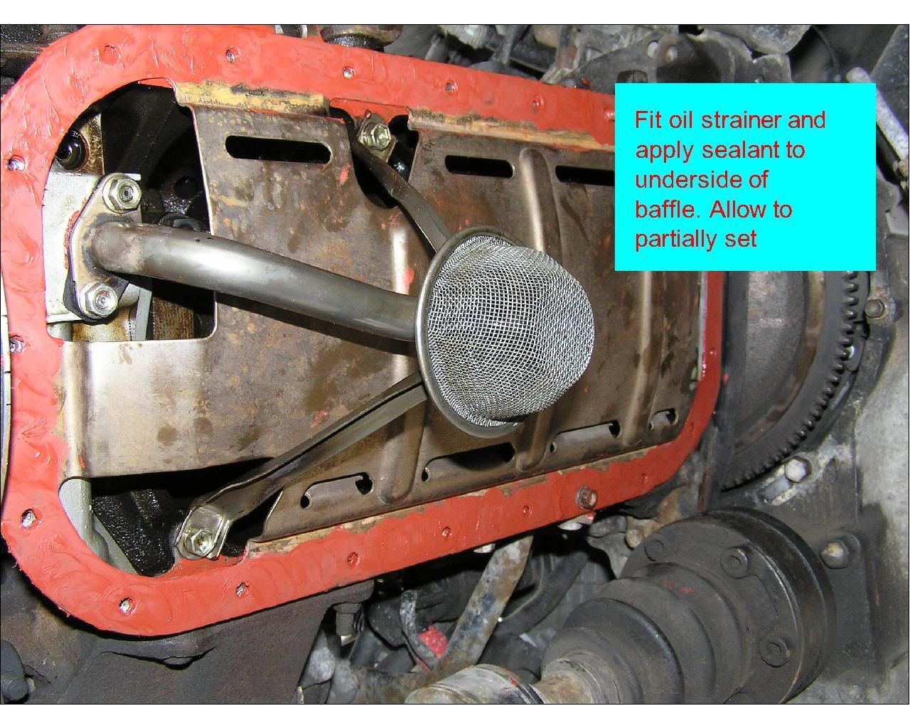
30) Apply sealant to underside side of baffle and allow some time. Fit oil strainer pipe.
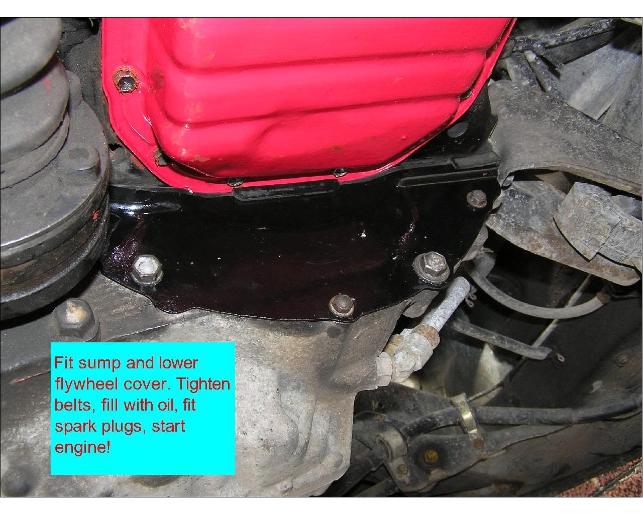
31) Fit sump and lower flywheel cover. Fill with oil. With spark plugs removed crank the engine over for a few seconds until oil pressure starts to rise. Refit spark plugs. Start engine!
 |
| |
| User comments |
| rootes: Wed Nov 07, 2007 2:49 pm |
|
| Icsunonove wrote: |
| Rootes wrote: | | may be better to clean the shell in the journal and lay the plasitgauge in there before fitting so do not have to use grease / oil. |
With respect I don't recommend this. You may get an irregular shaped extrusion and a false result. Always use some grease! ![[thumleft]](images/smiles/icon_thumleft.gif "thumleft")
|
with respect ![[Wink]](images/smiles/icon_wink.gif "Wink") plastigage themselves say NOT to use oil/grease and to use when shells and journals are clean and free from oil - using oil/grease is the reason yo will get a funny squish.. plastigage themselves say NOT to use oil/grease and to use when shells and journals are clean and free from oil - using oil/grease is the reason yo will get a funny squish..
remember the gauge is there to measure the gap between the journal and bearing and not the gap inclusive of a film of oil/grease
they point was why stick the gauge to the journal with grease when you can just pay it in the shell and let gravity keep it there until you are tightened up
BUT in this situation a remnant of oil is going to be hard to get rid of so what the heck and this is still a great article and loads less hassle than a full engine apart rebuild
regards
Si |
|
|
| rootes: Wed Nov 07, 2007 2:57 pm |
|
| Icsunonove wrote: |
| Rootes wrote: | | after all it is plastigauge is a 'gauge' and not an instrument and thus is a gauge / indication rather than a measurement.. |
You don't need to know the exact measurement of the journal and the shell. What you are looking for is the clearance. In this respect Plastigauge is more accurate than a standard internal and external micrometer. |
Of course you are looking for the cleareance as that is the whole point of the excercise
I was not disputing its accuracy (they are very good) - but slightly padantic point there is a difference between a gauge and an instrument.. but in this case used correctly more accurate than using mics
I now step down off my step of pendatry..
Si |
|
|
| Icsunonove: Wed Nov 07, 2007 8:04 pm |
|
[Pedant head on]
| rootes wrote: |
with respect plastigage themselves say NOT to use oil/grease and to use when shells and journals are clean and free from oil - using oil/grease is the reason you will get a funny squish..
remember the gauge is there to measure the gap between the journal and bearing and not the gap inclusive of a film of oil/grease |
Si, sorry to labour the point ![[Embarassed]](images/smiles/icon_redface.gif "Embarassed") , but that's not correct...... , but that's not correct......
From Plastigauges website: http://www.plastigauge.co.uk/
And instructions:
| Plastigauge website wrote: | | Remove the engine sump cover to reveal the big-end and its retaining set-screws. Remove surplus oil and release the big-end shells by unscrewing the set-screws. Apply a smear of grease to the journal and small quantity of silicone release agent to the shell. |
[/pedant head on] |
|
|
| rootes: Thu Nov 08, 2007 10:58 am |
|
Ok fair point, no oil though and those instructions are for a full engine out on the bench job
as a note plastigage is a US product made by Hastings, the US instructions spec no oil or grease, though interestinly it does mention use use of silicone release (never noticed that before)
the US instruction also has a little section re crank weight for those checking clearance in situ - designed for light aircraft users.. it does say support weight of crank.
when I get chance I will scan them and put them up..
BUT the main thing is that practically i can't see the use of grease/no grease etc affecting things too much anyway, especially given the inherent tolerance in the clearances..
so best let people do what they feel happy with. but if you do use grease only use the absolute thinnest of smears and in possible for the insitu bearing change try to remove all the oil.
Please don't think I am trying to pick apart your article it is very good and great if you are doing an insitu change - just I have used plastigages a lot in industrial settings and they are great and accurate, but lots of things can make them less so, like oil, poorly fitted shells, oval journals (can check by doing two or more clearance checks but rotating crank a little in between checks) etc etc.
as a note you can also use round strips of lead to do the same, though plastigage is simpler and comes with a nice little chart etc
plastigage is also oil soluble so if you leave a trace on the journal is wil dissovle anyway - though best to remove properley
Si |
|
|
| Icsunonove: Thu Nov 08, 2007 1:26 pm |
|
| rootes wrote: |
as a note plastigage is a US product made by Hastings... |
![[Confused]](images/smiles/icon_confused.gif "Confused") It's a British invention and a British product It's a British invention and a British product |
|
|
| Page 4 of 0 |
All times are GMT
Goto page Previous |
Powered by Knowledge Base, wGEric © 2002 PHPBB.com MOD
This script (Knowledge Base - MX Addon v. 1.03e) is modified by Haplo
|
Powered by phpBB © 2001, 2005 phpBB Group
|