


Throughout this install I had the appreciated help of a good friend, Andy along with lots of coffee and tea � thanks for all your help. This is written in the first person but Andy was pivotal to all of the steps, it's definitely a team effort.
InsuranceCall me old fashioned but I like to make sure my Insurers know all about the car (usual reasons). I insure with Dorset Insurance. I gave them a call and explained the TC, what it did and who made it.
They asked for confirmation of the phone call in writing and said there would be no increase in the insurance premium. I'd have been disappointed if there was an increase, but at least they know and I've a clear conscience about it.
The PackageThe traction control was purchased as part of a group buy arranged by some Nissan 300ZX owners. I know of one other MR2 driver who took advantage of them and joined in.
The TC is made by RaceLogic. There are options available in addition to the standard unit. The options on mine were variable slip (5% increments between 0% and 20%), and launch control. This made for a little extra wiring, but nothing horrendous.
The kit arrives with most of the loom pre-wired. They provide a pair of mating connectors, loom, control box, traction control system, crimp pins, instructions and software (for any DOS machine with a serial cable). Everything was there except the tools.
First point to make. The loom is far too short for installation on any type of MR2. RaceLogic have installed this system on a 91 Turbo MR2 recently and mailed me to let me know they are to increase the length of the cabling for the wiring loom. If you order one from them, point out it's for an MR2 and you should get the longer loom included.
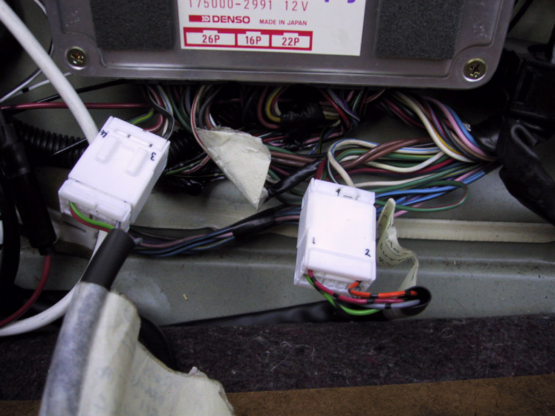
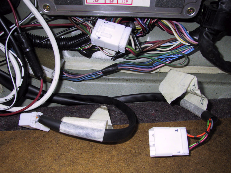
InstallationTwo things to mention. Firstly they include a set of connectors and crimp pins. The use of these allows you to remove the invasive aspect of the TC. In short you cut the signal wires for the EFI between the Engine ECU and the fuel injectors.
Using the crimp pins and connectors rejoining these severed wires is simply a matter of unplugging the TC control box and plugging the ECU/Injector plug/socket together � well worth doing. (see Tcin.JPG and TCOut.JPG)
Secondly, as I mentioned on mine the loom was a tad short so I bought some multi-core cable � 5amp 3 core mains cable as it happens. Running the cables in takes time and effort � by far the most time I spent on this project was running cables in. Plan where you want the controls, and stick to it � I didn't.
The TC wants connecting to the Engine ECU (injector signals, RPM and power) and to the ABS ECU. A visit to my local Mr. T (whom I find really very helpful � am I the only one�?) resulted in me getting hold of the ABS ECU pinout and location details. I have the pinouts for the Engine ECU from the BGB online.
I also have a diagram from Dino for the ECU RPM signal. More of that later, but thanks to Dino.
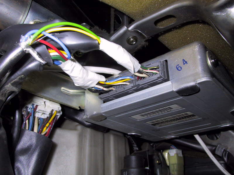
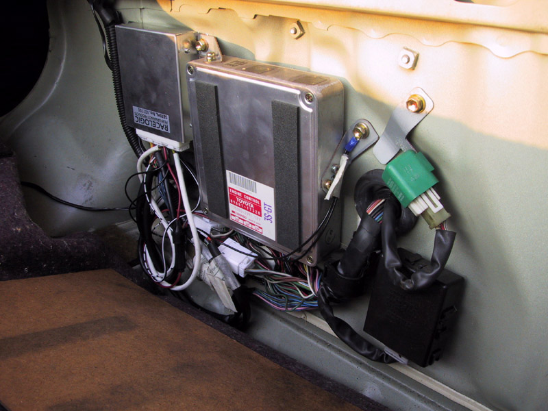
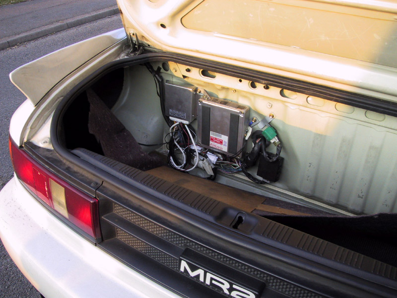
I placed the TC system box alongside the ECU in the boot of the '2. This made the most of the space in there. There is a seal on the case for the TC system. If you bolt it down too hard this can tear � as did mine. If the seal is broken, so is your warranty � Doh!!
Once the install was complete and the cables had been run in and joined up came the moment of truth � turning the engine over again � and it all worked!!!!
In UseWhen first powered up the unit needs to be taught a thing or two. Usually driving a U shape path with full lock on for the turn does the trick. However, if your wheels have different rolling diameters you'll find this doesn't work too well.
It didn't work too well for me so I had to use the terminal software and a laptop on the serial connector to fix the problem. Tell it the rolling diameter of the wheels; repeat the calibration steps and it works much better.
My one remaining problem is the car misfires a little when pulling away gently. I am working on clearing this up, but I think it's more a reflection on the setup than it is on the TC.
The last thing I did was to check on the sequential injector setting. By default this is turned off. I turned it on and tested things out � the engine stalled. The problem is the cut patterns used also needed setting.
So, I�ve a 4 cylinder engine so I programmed the first cut to miss every fifth power stroke, the second to miss every third power stroke, and the third to miss every other power stroke � except one.
The reason for this is to ensure the cylinder that is misfiring moves between the four cylinders on the engine.
I haven't really had enough bad weather to try it out fully, but initial impressions are good. The power cut (when it happens) is gentle and progressive, becoming more noticeable the more you abuse the loud pedal.
In the wet and the dry the system allows you to corner with your foot flat down and without any attempt to slide. Providing you go into the corner at a reasonable speed, you can floor it all the way around without worrying about the tail end popping out too much.
The variable slip allows you to slide the tail end if you want with confidence that it will never (correction here, read not very often instead of never) get away from you. The launch control works but isn't really for use on the roads (at least not by me, not after last time).
I'm happy with the system and pleased I bought it. Part of that is the discounted price due to the group buy, but the majority is from the system itself. Excluding the slight misfire on take off the system is unobtrusive when driving normally.
Even when the system starts cutting power the progressive approach taken is subtle enough to go unnoticed. It will increase the cut if it can't control the wheel spin initially, and will continue to make the power cut more aggressive until it brings the wheel spin under control.
Remember � you can always turn it off if you want to. I find it doesn't get in the way, so mine is left on with 10% slip in the dry, and 0% slip in the wet.
Time for the fitting details along with piccies where I can fit them in. I didn't take the piccies as the install progressed � I forgot my camera that day � Doh! Instead I've fitted the TC and put the controls where I want them and then taken the pictures.
PreparationThe installation manual gives a list of tools required. I used;
The installation instructions are excellent. I had two issues that I'll mention here and then leave (finally). Firstly, the wiring loom was far too short, although RaceLogic have a longer loom now for MR2 owners.
Secondly, the connection between the slip/launch control and the TC system box weren't easily understood � so I mailed RaceLogic and got the answer. I should have read the Manual again. In short, connect all the wires up � the ones that remain match colour for colour to the slip/launch control box.
The wiring loom of the '2 stays pretty much intact with this, but you'll need to identify which cables are needed from the ABS ECU and the Engine ECU. Since the Engine ECU is vastly expensive and all the connections can be removed � I removed it and set it aside throughout the installation.
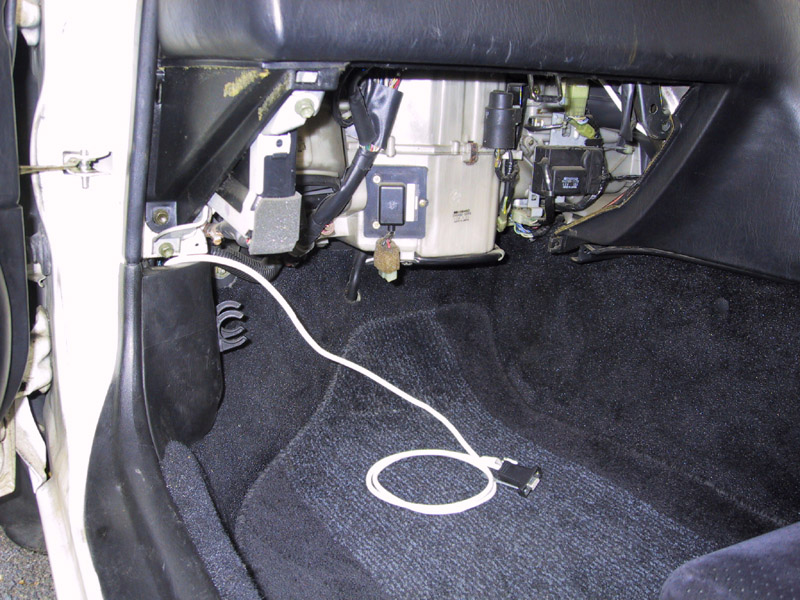
Wiring path from boot to the cabinThe electronics live in the boot adjacent to (and mounted off) the Engine ECU. The serial/diagnostic port, diagnostic LED, slip/launch control and ABS sensor cables all need to be run from the boot through to the cabin.
The ABS, power, ground, RPM and injector input/output cables were long enough. The other cables were replaced with longer cables that had a fresh set of crimp pins attached to them and were plugged in to the pre-wired loom to replace the cables that were too short. Thanks to Ben from RaceLogic for sending me replacement crimp pins.
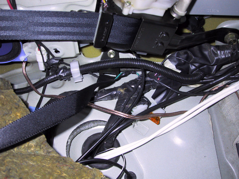
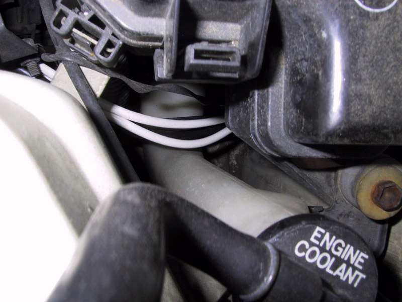
The cables ran from the boot through the large grommet next to the ECU into the engine bay. It continued along the left hand side of the engine bay, under the air filter box and followed the main car harness through the firewall/bulkhead into the cabin.
To get to this I had a nightmare. I removed the outer vent cover from the left hand side of the car � to no use. In the end, the air filter box/assembly came off and that provided the best access.
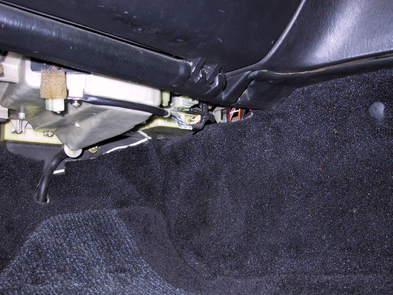
I removed the center rear console, center tunnel cover and the left hand side door sills. The rear console and center tunnel cover had to come off so I could place the diagnostic LED where I wanted it (which was just below the gear shift, adjacent to my alarm LED).
I ran the diagnostic LED cable behind the "carpet" behind the seats along to the center rear console, under this and along the existing wiring loom to reach the gear shift boot/cover. I drilled a hole in here and plugged the LED in, then put the covers/console back in place.
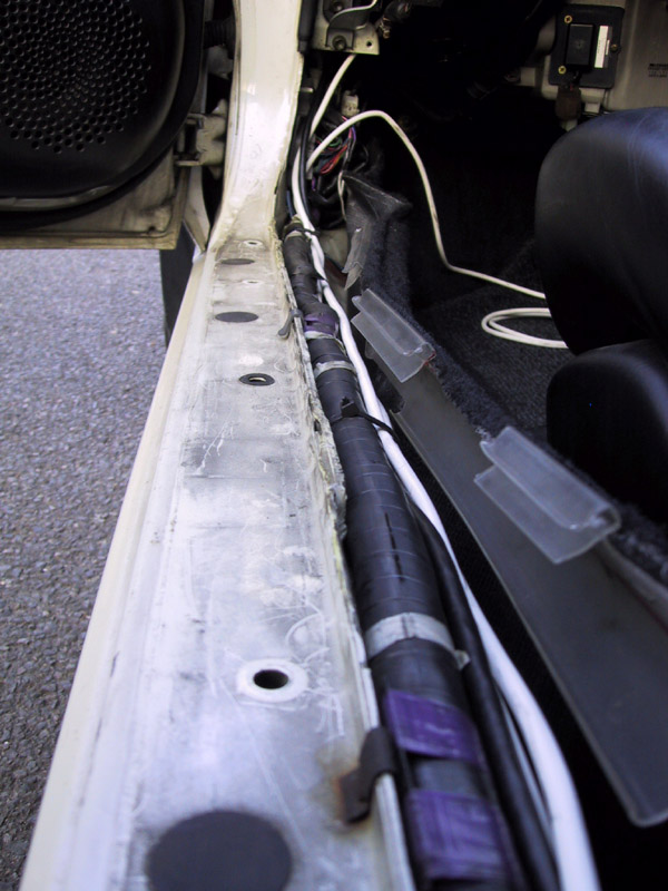
The remaining cables all ran alongside the existing loom beside the left hand side sill between the door sill and the passenger seat, emerging at the left hand side of the dashboard.
The cables were separated out. The slip/launch control cable was routed behind the ABS ECU and up and across to below my single DIN stereo head, popping out in the front center console and had the slip/launch control box refitted � where it lived for a short while.
The ABS cable followed the same path up to the ABS ECU where it was cabled in to the previously identified wires.
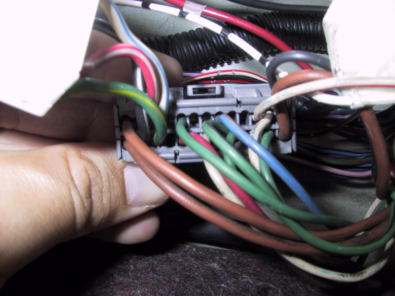
ABS sensorsThe TC needs feed from the cars ABS wheel speed sensors. There are two different types (all this is in the manual), but my '2 uses the two wire sensors with a signal shield going to ground. I chose to use the Positive signal wire from each ABS sensor.
All the sensor cabling comes together and plugs into the ABS ECU. This box lives under the dashboard behind the glove box. If you remove the entire glove box assembly you'll see the fella sitting upside down on the underside of the dash board.
The pin-outs I have gave me wires that had colours that matched those on the ABS sensors (I traced them to be sure). Be very very careful here. I know of at least one car, same model as mine, one year younger, with completely different pinouts on the ABS ECU.
Don't know why, but they are (I think it�s because my ABS is advertised as four channel, but the wiring diagram suggests the rear wheels share the same ABS pressure release solenoid, so in fact it is only three channel � newer ones may actually be four channel).
The pinouts I used are�.
| Front Left +ve | pin 25 (white/pink) | |
| Front Right +ve | pin 37 (white/pink) | |
| Rear Left +ve | pin 13 (white/pink) | |
| Rear Right +ve | pin 6 (white/pink) |
Please make sure you get the correct pins. I stripped the insulation from a short section of each cable (without cutting the cable), and wrapped the corresponding wire of the TC loom ABS feed on to each bared section.
When I had wrapped them all and I was sure they were the correct cables I soldered them up and wrapped them in electrical insulation tape. Re-wrapped the bundle and tucked them back up where they belong. I unplugged the cables from the ABS ECU during this stage. Back to the boot. The pinouts on the Engine ECU were as follows�
| Injector 1 | pin 12 (26Way) | |
| Injector 2 | pin 11 (26 Way) | |
| Injector 3 | pin 25 (26 Way) | |
| Injector 4 | pin 24 (26 Way) | |
| Power | pin 12/13 (16 Way) | |
| RPM | pin 3 (26 Way) |
In the boot the same method of baring the wire, wrapping the appropriate cable from the TC loom and then soldering the wrapped wire can be repeated for the power feed and the RPM signals � so I did, and I re-wrapped the cables in PVC insulating tape as I went.
I attached the ground strap to one of the mounting bolts on the Engine ECU supports. This is a good chassis ground and seems to work fine.
The power feed wire is one of a pair in the connector to the Engine ECU. They both look a little weedy but again they seem up to the job. As the manual says, the power must be ignition switched and must not go to ground while the starter motor is running.
Finally a note about the RPM signal. Thanks to Dino for helping me out with this signal in particular, and to all from the IMOC-UK list who gave helpful replies. I couldn�t find a good source for an RPM signal; Dino did and sent me a diagram of how to find it.
Power up/TestAt this point is should be possible to plug the Engine ECU and ABS ECU back in to the car, turn it over and let it idle for a while. The Engine ECU needs to learn a few things (apparently).
You should have the ABS, RPM, power, ground, slip/launch control, diagnostic/serial cable and LED cables attached. The instructions in the manual are once again excellent when it comes to testing to make sure all the stuff works, so I won�t repeat what they say.
Fuel Injector WiringAll the connections so far have not been invasive. The TC has been taking signals or power from existing cables. This next step is one where there are no half measures; I had to cut signal wires from the Engine ECU to the injectors.
I used the plug/socket and crimping kit supplied with the system. They allow the system to be removed from the car, and the break between the Engine ECU and fuel injectors (i.e. Where the TC system used to live) can be made again by plugging the Engine and Injector plug/socket into one another.
I (Andy) spent quite a lot of time making sure the male/female pins were in the correct plug/socket and went to the correct wire. This is really very important. The system does not seem to (but I may so easily be wrong with this) care which Engine ECU/Injector pair goes to which TC input/output pair, but it�s crucial to make sure that the injector signal from the ECU for each cylinder goes to the input side of the TC such that the corresponding output signal goes to that Injector.
It�s difficult to describe, read the manual � they put it better. The main thing is to make sure that the injector signal wires match. You don�t want them to cross so that for example the signal for Injector 1 from the ECU goes into the TC and comes out going to any injector other than Injector 1 � bad things happen.
Anyway, the wires were cut and the crimping pins were secured onto the bare ends and placed into the correct plug/socket and correctly aligned. The corresponding socket/plug were crimped onto the wiring loom of the TC system.
To make sure all is well I fired up the engine with the TC out of the link, so the cut in the injector signals was joined by the plug/socket attached with the crimp pins.
Finally, break the plug/socket and insert the TC system in between them. Once again I fired up the car � and it ran fine. Now time for the checks�
Testing, setting up and running for a whileThis wasn�t as much fun as it should have been for one simple reason � and I overlooked it! The front and rear wheels are different sizes, this gives the TC system the wrong impression about a few things � I�ll explain why.
You may have noticed there is no mention of which ABS sensor goes to which TC loom input. So long as all the ABS sensors are connected to the TC loom ABS feed all is well.
There are defaults set up in the TC system to tell it which feed goes to which wheel, and my limited understanding is that there is some nifty coding in there that helps it choose which is which (although I may easily be wrong � again).
This doesn�t work if the wheels are different sizes as it makes assumptions about the rolling diameter of each wheel to determine which hare on the inside of the turn and which are on the outside.
I�m fortunate enough to have a laptop supplied by work (and unfortunate enough to have to use it at all hours � still, it has it�s uses) which I plugged into the TC system and used some terminal emulation software to talk to the TC system.
They bundle software to do this � but mine works under Windoze. I used this to set the correct wheel diameters and set which wheel is which (reference - front, driven - rear, left and right).
Once completed I calibrated the system (they tell you how in the manual). I did this at my work car park one morning (it�s big and empty). That same day just before lunch time it rained.
I tested the varying slip and launch control that lunch time in the same car park (as I said, it�s big and empty) in the wet. The fun began and I haven�t looked back since!
Things to solveTwo little things are niggling me about this � and they are very minor. Firstly, when pulling away from a standstill gently, the car misfires early on but it clears and it pulls away fine from then on � I�m sure this is a configuration thing and nothing to do with the overall function of the TC (** Fixed this, see below **).
If I need to get away in a hurry the launch control works a treat, but as I said earlier � I don�t use that much.
The last niggle is the software. It looks really good in the manual and sounds very helpful � but, it only runs under DOS, and then only on COM1. My laptop doesn�t run DOS, and doesn�t have COM1 available. Perhaps a Windoze version will appear soon�..?
The final change I made was to move the slip/launch control box. Ben (RaceLogic), if you read this it�s a nicely engineered box, but I want it to be subtle, and I couldn�t find anywhere to hide it � sorry for what follows�
I took the slip/launch control box to bits (bye bye warranty I guess) and mounted the variable slip control in a circular push out below and to the right of the steering wheel.
I drilled some more holes in that area, one for the launch control button, and another for the red LED that shines to say the system is turned off.
The final step was to wrap everything in PVC insulation tape � there are bare wires/connectors in there. It�s fine when they�re well encased and protected in the original box, but when they�re mounted on the dash they are just too vulnerable.
The VerdictOnly my opinion, but I am very pleased with the system and its performance. I don�t drive the car as hard as others I�ve seen and I tend to keep the speed down these days, so perhaps if driven harder it may behave differently � could be better or worse � I don�t know but I�d put a few bob on it being better the harder the car is driven.
For me it does all I wanted. It allows me to let others drive the car knowing that if they get silly with the loud pedal going around corners then the TC will keep them on the straight and narrow.
I�ve pestered RaceLogic a few times during this install and found them to be responsive and helpful. They listen to people, an example is their preparation of a different wiring loom for �2 owners.
It�s only a minor change for them, but it would have saved me loads of time. If you go for one of these for your �2 remember to let them know what it�s for and they�ll probably be able to give you longer wires.
When the winter cometh I�m sure I�ll find it really useful, but now in the mid-Summer I don�t want to think about winter. For now I can accelerate from junctions even on wet greasy Summer roads knowing if the back end does start to slide it will be controlled to whatever slip I�ve set � it�s like having a safety net (one that noone else can see).
I can leave behind the scary moments I have had at particular roundabouts and T junctions. The response is immediate, the power cut is smooth and progressive, and the return of the power is also smooth and progressive.
Bring on the Elvington Track Day � and let the heavens open!
I decided to sit down with a laptop plugged into the TC and their Manual to see if I could fix this misfire on pulling away problem. The good news is I have, and this is what I had to do.
Firstly, I am prepared to be corrected on anything I�ve done here. I read the manual and followed their suggestions, but I may have misinterpreted them.
My system has a clutch switch input which will allow you to power shift without removing your foot from the accelerator. That seemed to be enabled. I�ll plumb it in one day, just not now. So in the software settings I disabled this option.
The 3S-GT ECU drives sequential fuel injection, firing each injector individually and at the right time. The TC was set up for non-sequential injection � so I changed this also (mentioned this earlier, but I thought I�d mention it again).
The cut tables were blank for cut levels one, two and three. I did set these early on, but I�ve modified the cut pattern to make it more progressive than it was.
I�ve set the maximum difference between wheel speeds to 70kmh (a rough guess, it can be changed). This allows glitch sensing to work and ignore extraneous pulses which if true would suggest a wheel speed difference of in excess of 70kmh.
The system now works perfectly. It pulls away even under heavy throttle without any excessive wheel spin. The engine never misfires unless the power is such that the wheels could start to spin.
Update 2 - Results of an airfield day and skid-pan session
The TC has been installed for a while now and it's been relegated to something that just happens. All that changed when I had the chance to push the TC to the limit on two very different surfaces. One was dry and fast, an excellently organised and very friendly track day at Elvington near York, the second was at an equally friendly skid pan session courtesy of Essex Police and some rather good organisation. Both thanks to the IMOC and a few individuals in particular.
Elvington
There are excellent articles describing this in much greater detail than I can remember so I'll leave the description to them, however Elvington is an old airfield, it's a big wide open space with concrete/tarmac and grass, plus cones for target practice (sorry, marking out the track). This was the site for my first track day and I thought it would be a good place to test the TC.
Following the advice I started off slowly and built up the speed. As I speeded up I didn't notice very much. The car was running well and cornering well. If I hammered it into a corner I drifted wide. All was well so I decided to turn off the TC to see what difference it made. Surprisingly I only noticed two differences.
Firstly the cars handling was just the same, it made no difference to the handling of the car. The two big improvements which I must attribute to it were in starting off when re-joining the circuit, and accelerating through the corners.
With the TC off the car felt much slower. This is undoubtedly down to my lack of control and erring in the side of caution. I accelerated harder and harder until I lost it at one of the faster turns and span. Even at that point the car felt slower than with the TC on. I switched it back on and sure enough it felt faster around the track.
When accelerating to join the circuit I tried the launch control. The car pulled away with a little wheel spin (15%), but nothing massive and I was heading into the first sweeping corner too quickly. I turned the steering wheel and hoped - it went around ok.
Overall the TC made the car feel much faster. I don't know if this is actually the case as it wasn't a timed event but others with TC agreed. It was a delight to floor the loud pedal in a corner and let the TC sort everything else out. The car power drifted our of the corners and was perfectly lined up to accelerate along the straight. The snag...? The only one I felt was that I was going into corners too quickly due to coming out of the previous corner foot down.
Essex Police Skid Pan
This was a half day session and was held at Essex Police skid pan in Chelmsford. The circuit was a small oval with grease, oil, and ramp at one end, and a rain machine that kept everything wet. The surrounding grass was banked and looked a little unforgiving. For each session a Police Driving Instructor was in the passenger seat giving advice and guidance.
I'm impressed with the handling of the 2 on this surface. Going into a corner too quickly and it understeered. Other than that it was solid and quite happy to toddle around the track. Give it a bit more power though and it's a different matter as the back of the car slides out and you find the car pointing into the apex of the corner. A blip on the throttle in second is all it took, a warning for me when the Winter arrives on the roads.
So, the TC. I struggled to get it to do anything to the point that my passenger suggested I'd just been sold a dial and an LED! I could still throw the back end out at any time and I was confused. I had a look at the revs and speed and realised that I was going too slowly and the revs were too low for the TC to become active.
I tried to pick the speed and revs up, but by the time the speed/revs rose enough the rear wheels were always spinning. I did get the TC to cut in a couple of times but I was occupied with the understeer induced by the extra speed. I wanted to throw the back end out to get around the corner - but the TC stopped me. I gave up shortly after this and turned it off.
Overall on this surface the TC didn't really do much. This is due largely to the low speed and low engine revs. I could drop the speed and revs at which the TC comes to life, but this depends on the ability of the ABS sensors to work at slow speed - and mine don't too well.
The Verdict....
I suppose I should have been able to work this out, but it took some driving for me to realise. The TC will keep you in line from low speeds and revs upwards providing the back end sliding out is due to excessive application of power. At very low speeds (for example driving around a car park, or turning into a very tight junction) the TC doesn't do anything much. I must stress this is due to the configuration - it can be changed, but there must be a point at which the TC decides you're going slowly enough to be on your own.
When you're at this point - you are on your own. At least the low speed allows time to recover or at least limit the slide manually. As you go faster the TC becomes active and that safety net is back. I'm still happy with it and I'm much more confident now I know it's limits and how it behaves in sliding conditions.
I was lucky enough to take the '2 to Nurburging at the beginning of August 2002. I did a few laps, the first lap I did was in the wet, the remaining laps were in the dry with varying amounts of grip. The 'ring is a long and unforgiving circuit and I treated it with a great deal of respect - I stayed well within what I thought I could do.
The wet lap was the first lap I've tried at the 'ring and I was taking it very carefully. I've found from experience that using the wet setting doesn't really give much scope for accelerating hard in the wet - so I set it to 5%. The back of the car felt solid, if anything I was having problems with understeer. Turning into a corner and accelerating around it would push the front of the car out away from the apex of the corner.
In the dry I pushed things a little further and found that with the slip at 10% the car felt more balanced, drifting around corners under power. With it set to 15% there's a little bit of oversteer - enough to have a play with at speed and it gives more options to get the power down when cornering at speed and seemed to give more feeling to the drive.
So, to finish this up the variable slip of the TC from my experience is well worth getting. It seems to change the handling of the car.
0% to 5% is a little harsh but good if you want to err on the side of caution. Tends to understeer under acceleration around corners. 5% to 10% good for normal driving. Tends to drift under acceleration around corners. 10% to 15% good for playing on tracks, etc. Tends to oversteer under acceleration around corners but easily balanced on throttle. 15% to 20% good for practising skid control on gravel, skid pan, etc. Oversteers, more difficult to balance on the throttle.
Summing up. I've been using the TC for a long time now. I keep the TC set to 5% in the wet and 10% in the dry and leave it on all the time (except on the dyno and when it's in for an MoT).
Update 3 - A trip to the Nurburging Ring
Click on an image to see a bigger version
| ECU |
| ECU |
| Cabin |
| ECU |
| Engine bay |
| Engine bay |
| ECU |
| Stock Toyota ECU |
| ECU |
| Glove box |
| Glove box |
| Glove box out |
| Left view |
| TC in |
| TC out |
| Controller |
| Shift LED |
| All in place |
| All in place |
| All done |