LED Interior Light
Description:
Categories: MR2 Mk1 Articles -> Exterior
Link to this article: Select all
[url=https://www.imoc.co.uk/app.php/kb/viewarticle?a=111&sid=9f9937fd30cf7d900f1e90881787e0d9]Knowledge Base - LED Interior Light[/url]
Ok Firstly you can use this method to create an LED board of any size shape etc and is followed up by my rear light conversion.
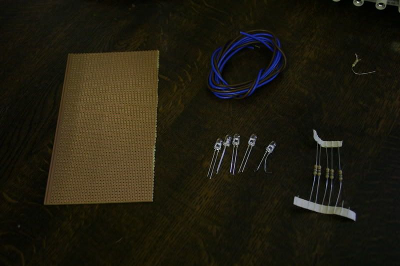
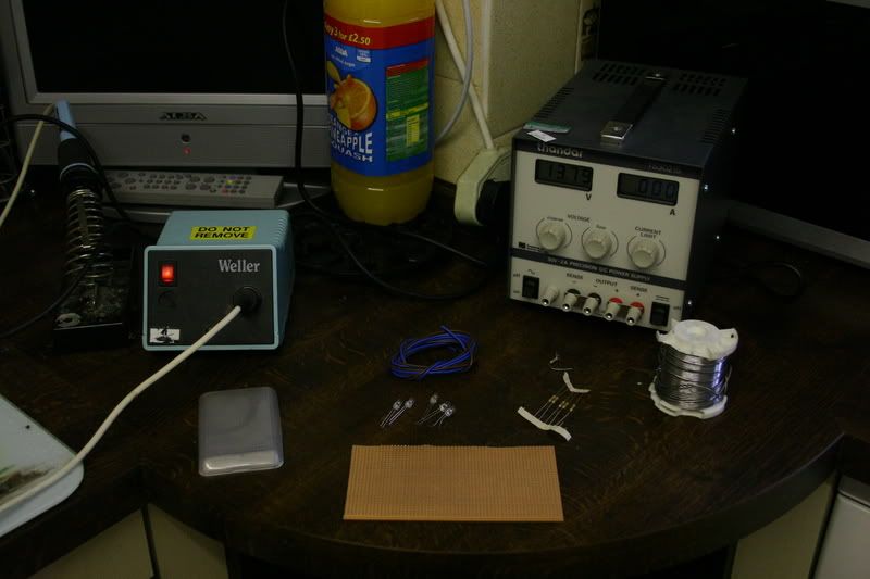
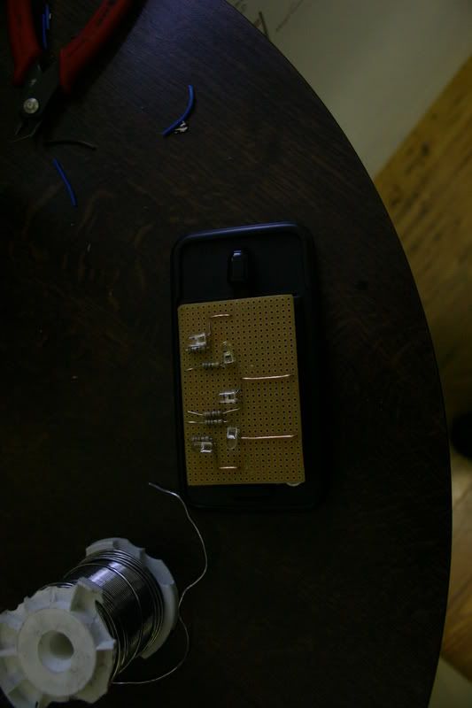
The equipment.
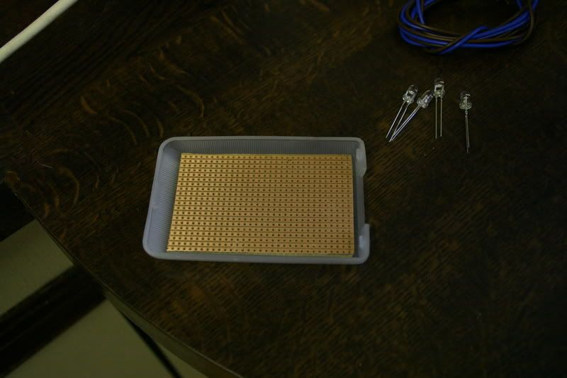
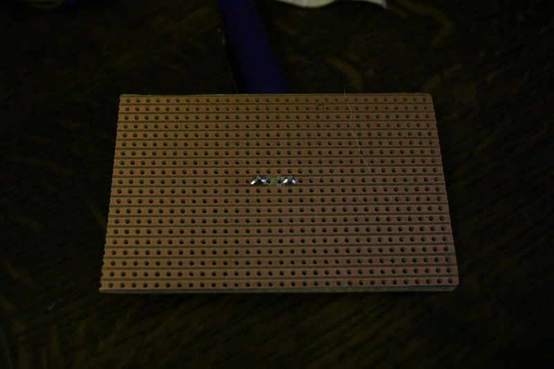
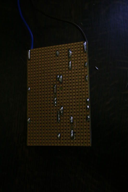
Firstly cut the board to shape.
Pop the first LED in place.
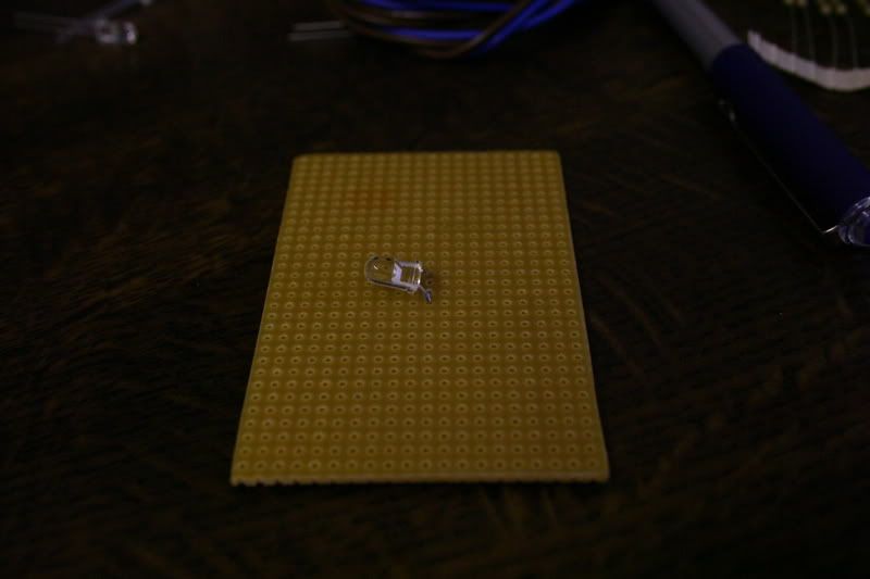
Solder it in place and break the track with the small drill.
Positive wire at the top.
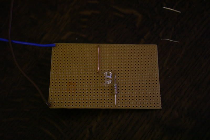
The resistor is calculated by voltage divided by current.
14.5V
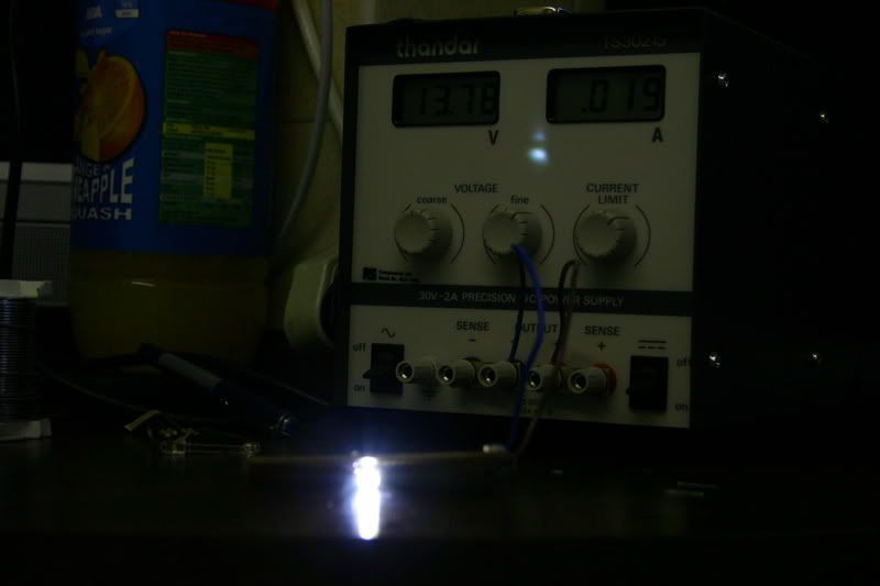
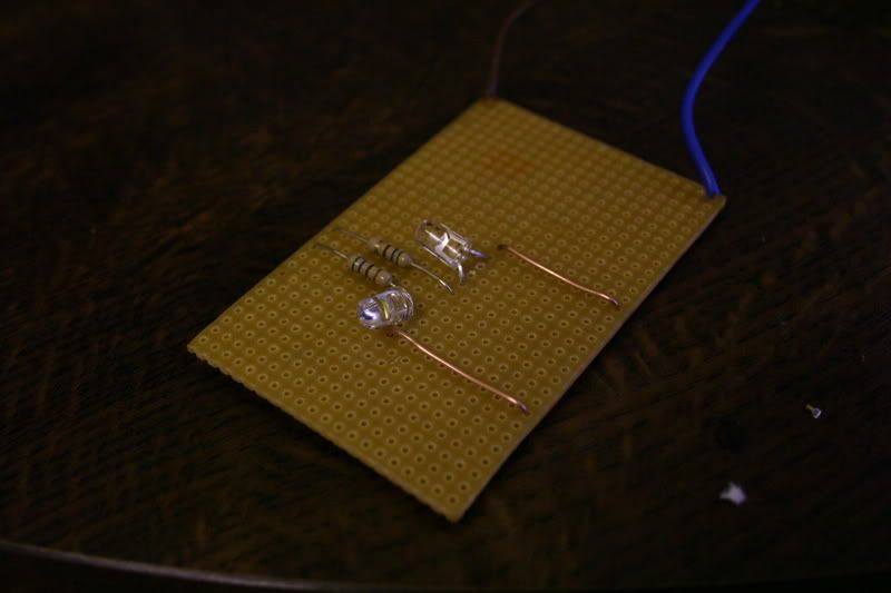
Connect to the powersupply with current limit set to 50mA for safety and one is running.
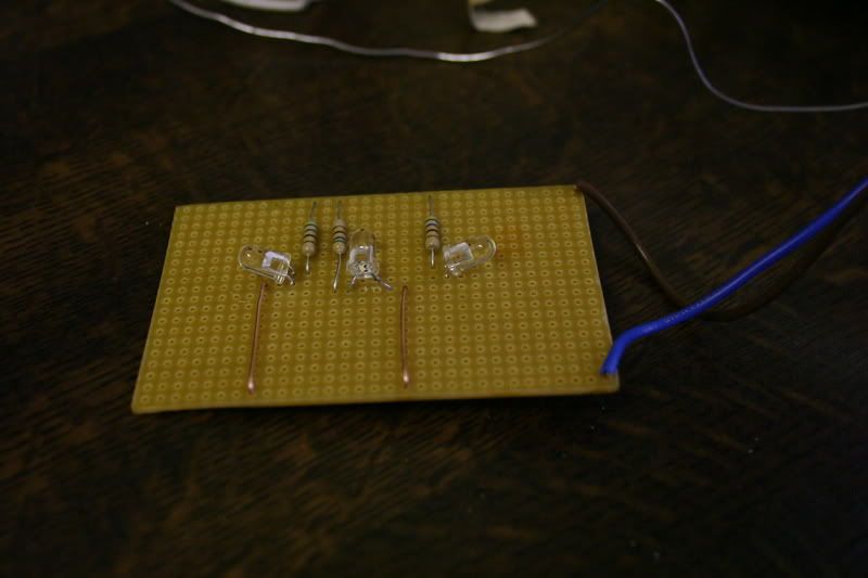
Next Place the second led in place and wire up as before
Then again until all are in place.
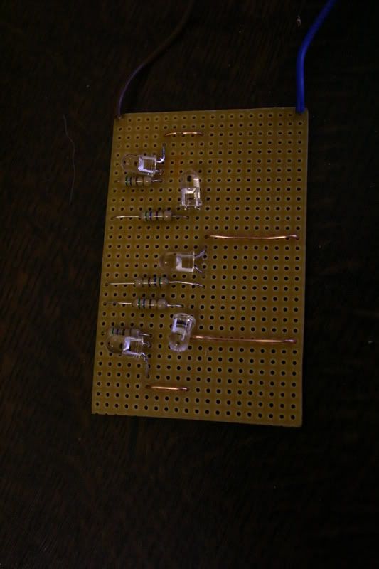
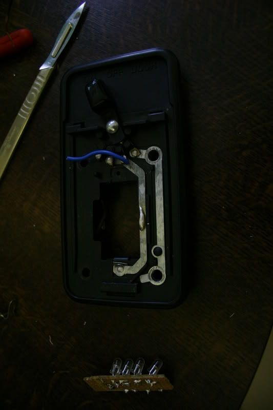
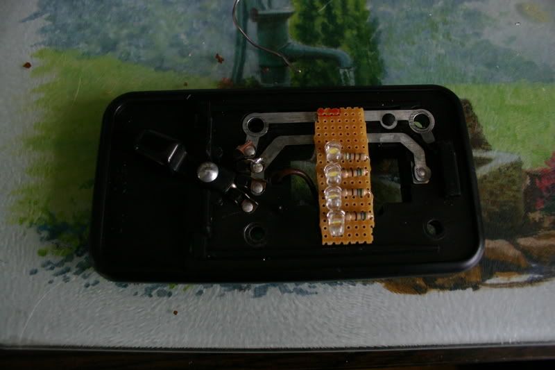
The interior light was taken out of the car by removing four screws and the connector plug.
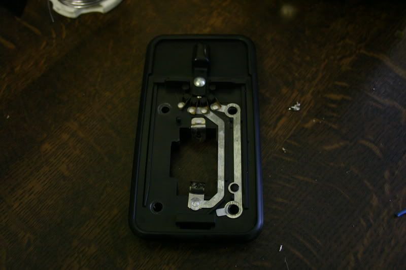
Positive wire soldered on ready for board.
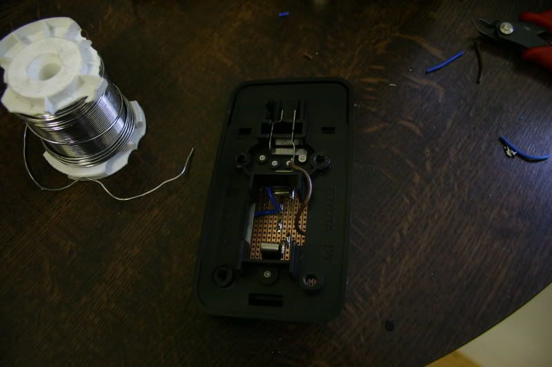
Negative wire soldered on and board put in place.
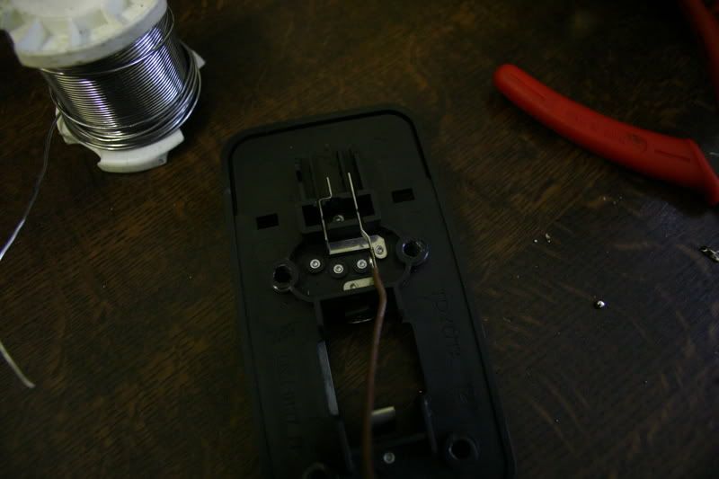
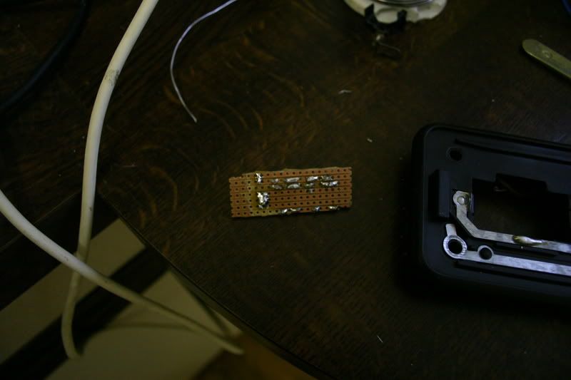
After all this work the lid did not fit on the light.
So a quick redesign and a much smaller board.
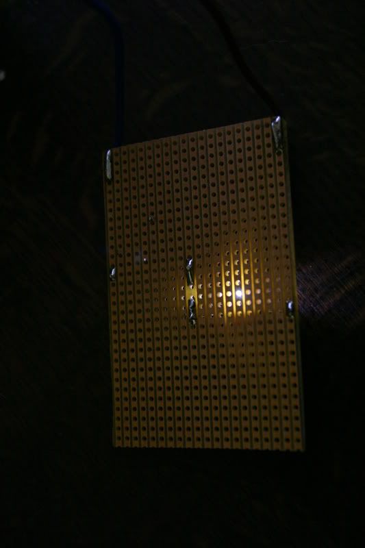
Notice the blob of solder on the metal rail.
The board soldered in.
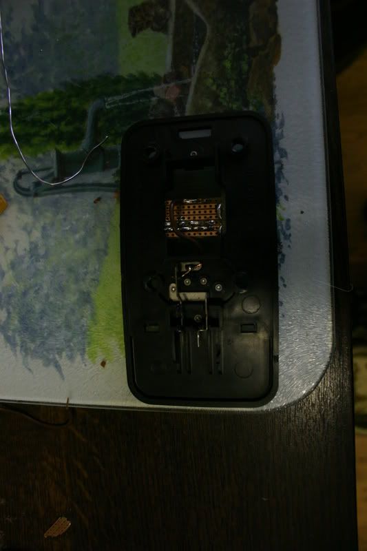
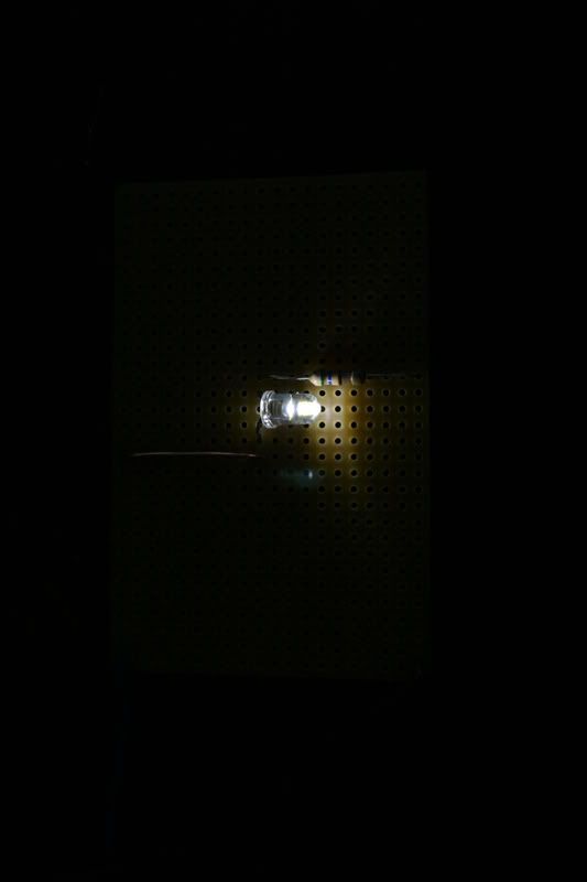
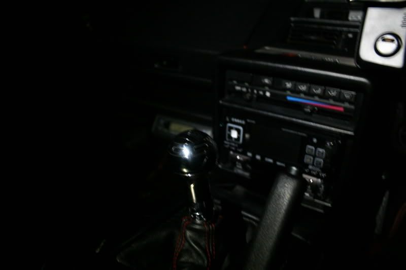
Screwed back in the car and tested.
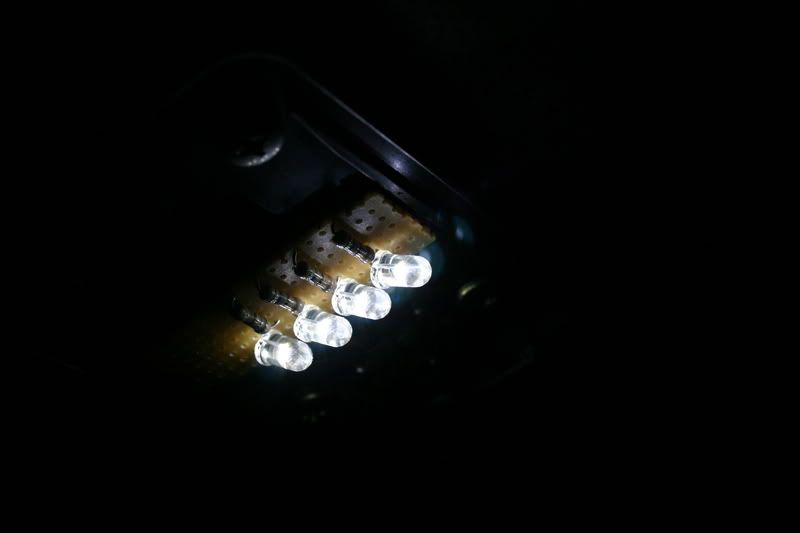
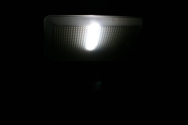
This is the light it produced.
And finnished with the cover on.
You can create any board of any size like this.